Sunday 16 June 2019

Engine and body

Today's tasks were;

Engine trial fit
Bodywork trial fit

Engine first. Well, it was meant to be, turns out someone up there decided rain was more important. I tried a few times, even got the engine in the air and almost into the car. But I didn't think rain was going to do the engine or electrics any good so I abandoned it. At least the garage got a bit of a clean!!

The bodywork was a little more successful, mainly because it's waterproof. I wanted to get it fitted to see how much of a gap there was around the panels. The first thing was that the front had to be trimmed. It was designed to fit a range of chassis shapes, so I expected it to need trimming. A quick centre point marking showed that the current cut out was nowhere near the middle, so a minute or so with the jigsaw took care of that!

Once I was able to drop the body down, it was clear that it needed a bit more trimming to fit. No biggie, it's expected. But again, I got fed up of the rain coming and going, so it went back in the garage.

So for the time being the chassis is on it's side, as the garage is intended for another purpose soon. I have a few 3D printing projects that I want to look at, so the first job is to learn Fusion. 

Friday 14 June 2019

Current progress and pipe fixing

A short update as I have a spare few minutes. The side panels have been cut in line with the back panel, and folded to allow a 20mm section to be rivetted to the back panel. The sheet metal brake that I cobbled together and initially thought was 'a bit rubbish' has actually worked really well. I think the only issue I had with it was the lack of a sturdy base, but it turns out clamping it to the chassis itself provides more than enough stability to fold the aluminium.

I've ended up with panels that are really nicely folded (I'm amazed how well they came out to be honest!), and will butt up against the back panel nicely. The next job will be to cut the notches out of the bottom for the seat cross members, then drill the rivet holes. The inner panels need a small crease added, the outer panels are straight so no more folding needed.

I think the engine fit on the weekend is out of the window though, the wet weather is (literally) putting a dampener on that task.

The next thought on my mind was pipe fixing. Inside the transmission tunnel I've welded some tabs that are intended to carry all the necessary wires, pipes, etc from the front to the back of the car. The tabs are quite substantial, and are done at quite frequent intervals in order to ensure everything is nice and secure. But while that provides the chassis anchor, I hadn't looked into the final fixing. For wiring this just needs to be some sort of protective shield with a cable tie, pipes need something a bit more substantial that is bolted in place.

There is going to be four pipes in total, two brake and two fuel. They will all be copper/kunifer pipes, hopefully I have enough! The runs from front to back are surprisingly short, maybe a couple of metres for each? The bigger issue is the fixing. The normal approach is for a small nylon bracket that the pipes can clip into, but they are hideously expensive (£20 for 10 the last time I checked!). But I now have a 3D printer, so I could actually print some. I'd have to design them from scratch, and I need to consider that 3D printed parts aren't as strong as nylon parts. But they are effectively free (ish) which is always good in the Locost theme!

The other option is P clips. As above, I had thought they were quite expensive, but someone has sent me this link;

https://www.amazon.co.uk/Black-Nylon-Plastic-Clips-Fasteners/dp/B01IHSEO5I/ref=asc_df_B01IHSEO5I/?tag=googshopuk-21&linkCode=df0&hvadid=256110

Which refers to P clips that are much cheaper. Less than £4 for 50 P clips seems to be a good price. Of course these are only for single pipes, but I was thinking for each fixing I could use a combination of four, laid out as;

qp
db

IE four different directions so the holes line up in the middle. I think it'll need some sort of stand off to keep the clips away from the tab, but that's not difficult.

Thursday 13 June 2019

Some thoughts...

Whilst I've been doing the panels, I have come across a few things that I need to remember for later.

Side panels. The GRP bodywork doesn't come all the way down to the side panels, there is a gap of several inches. In the demo car there was a curved piece of aluminium which I was going to replicate. Problem is, I'm out of aluminium. This isn't a huge problem, I couldn't have used the existing aluminium anyway. Trying to put a nice curve into 2mm aluminium would have been very hard work!! Once I have the measurements I'll order a 1mm sheet which should bend easier. It's only a decorative panel so it's not an issue.

Side panels 2. The bodywork attaches to the car at the rollover bar mounting points, and comes in at the corners where the occupants shoulders would be. From memory, this distance was shorter than the actual metalwork width, so once the panel has been fitted I'll need to trim that back. As with the side panels, this might result in a section that needs to be filled by aluminium.

Engine height. Hopefully this weekend I'll be getting everything out of the garage so that I can trial fit the engine. This will be so I can fabricate the mounts, and figure out how much space is available in the engine bay for everything that has to go in there. The main issue is how high to mount it. The general opinion is to have it as high as possible in relation to the bonnet. Even so, this tends to leave the sump hanging below the chassis, which is a good thing. But I don't have a bonnet, or at least I don't have an easily accessible one that I can use to measure. I am hoping that the trial fit of the rear bodywork will give me a height to work to. From there I can work out where to put the engine.

Front part of the rear bodywork. The main tub of the car is made from one piece, with a built in 'firewall' at the front that fits on to the chassis. As above it seems to be designed for a narrower car, (or deliberately moulded small to cater for most chassis variations) so the opening isn't big enough to fit over the bodywork. I'll need to open it up in order for it to fit over the car.

Engine mounting and 'the extra bar'. The plans have a section of a crossmember that is removed in order to allow the engine to fit. I've yet to figure out why, it seems like an ideal position to reduce some lateral flexing, and engine bay pictures suggest there is clearance between the bar and the engine. At the moment it's still there on my car, but if it gets in the way of the engine it will need to be removed.

Engine mounts. I have the original engine mounts from the MX5, and it makes sense to reuse them. The mounts themselves are an angled design that contain a rubber bush, so I think they'll be perfect for fitting. The Saturn plans actually disagree though, they say that a bush in shear isn't a good plan. I'm not sure why, MX5's have had them in that design forever, as have many other cars! I've asked the font of all knowledge, IE locostbuilders, lets see what they say. I did find a picture of an engine mount;


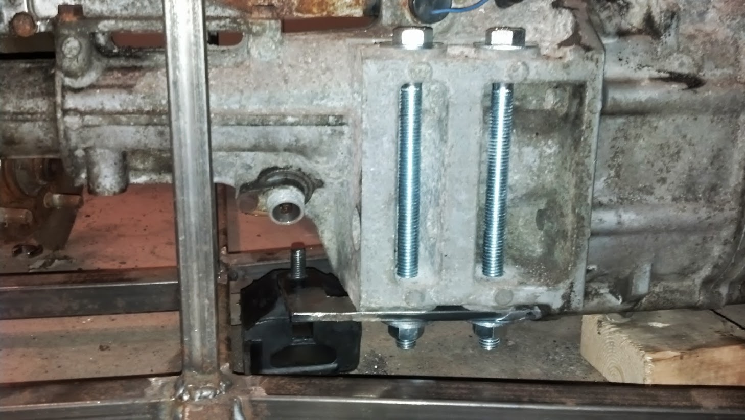
And a gearbox mount;