Well, I expected at least one downer on this project, although I did expect it to be DVLA induced. After removing the diff, and cracking it open, I've found it doesn't fit on the Talon diff cover. The mounting holes are on a circle that's approximately one inch wider than the diff. They're in the right place in terms of angles around the centre point, the screw threads are correct and the two stub axles fit nicely, but there's no way the diff is going in. I do wonder whether it's a difference between a 1.6 and a 1.8 diff, as the one in the picture is a 1.8 but mine is a 1.6.
I've emailed Phil to see what happens, I'm not sure what he can do though. At best a refund would leave me just out of pocket for the postage and packaging, but then unless he can make a new one to fit I'm going to have to go back to the original plans for the rear suspension. Which was what I was trying to avoid!
There might be a possibility that I can use a 1.8 diff, but keep everything else. That's if they bolt together...
Well, there is an update, rather quickly actually. Phil is putting together some CNC created covers, so hopefully I can arrange with him to swap my prototype one for a 'real' one. It should also fit the 1.6 diff, so win win really.
Oh yeah, and I've figure out my diff is a viscous LSD. Not as good as a Torsen diff, but better than a completely open one.
Saturday 14 September 2013
Sunday 8 September 2013
We have lift off!!
Everything stripped off the car, all bolts undone, and engine stand in position;

Take the strain...

And lift...

Rear wheels moved to where the front wheels used to be;

And done!

There was a slight miscalculation with the length, the exhaust hung outside the garage. So a bit more spanner action and the exhaust was off!! It was way too big to reuse, so the scrap man got that one.
So the garage is now full of wanted kit...

As well as unwanted kit...

So it's time to start getting rid of the unwanted bits. Everything went on MX5nutz first, a few nibbles but nobody local who could collect. And none of it can realistically be delivered. Over to Gumtree, and the wing mirrors and soft top have already gone, so that's £100. The panels are still to be sold, so fingers crossed. If not it'll go to Ebay, but I suspect that will be hard work.
Nothing else will happen with the build for now, with all that stuff in the garage I can't move. But I'm off to Ireland for a couple of weeks, so it will just stay there. I hope the empty shell can be removed before I go, I did have one place that wanted scrap metal but when I phoned them I found he'd moved to North Wales. Fingers crossed I find someone to take it.
Wednesday 4 September 2013
Chassis build
I've just noticed, I got so distracted by my donor strip that I hadn't logged my progress with the chassis. So the tunnel is done;
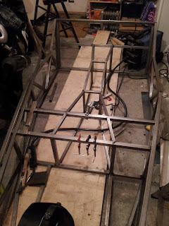
I'm quite happy with how the diagonals have gone in all over the chassis to be honest, I cut them all as matching pairs and they all fitted correctly with no trimming. That means that with the laser alignment checking the horizontals, the verticals are similarly accurate.
Anyway, enough chassis waffle, the MX5 is nearly stripped and might be losing it's bodyshell this weekend, so it's all steam ahead for getting the last few donor bits off the car!

I did have a bit of trouble with the diagonals on the seat back. For some reason I'd cut them identically, but where they met the suspension top mount on one side, it was a good inch or so off on the other side. I actually left this one for a couple of days, so frustrated with myself that the chassis was that twisted. I'd measured everything as close as possible with my eye, each of the horizontal bars on the rear were identical and the verticals were a perfect match as well. But of course, same length on parallel sides either makes a rectangle or rhombus; the former being good and the latter being bad.
I finally came back to it and had a good look at what I was doing. Then I found the problem. The horizontal bars are at different angles, the middle one being 'flat' to the seat back and the top one being horizontal. This means that the diagonals are cut at quite a sharp angle on either end, with a 'diamond' profile being presented to the top bar. I'd basically been measuring the wrong part, the wrong end of the diamond. Once I started comparing the centre of the diagonals rather than the corners, it all lined up. I now have a matching set of welded in diagonals, and there is roughly 1mm difference between the two. That does suggest there is still an element of error, but 1mm is a huge improvement over 1 inch!!
I'm quite happy with how the diagonals have gone in all over the chassis to be honest, I cut them all as matching pairs and they all fitted correctly with no trimming. That means that with the laser alignment checking the horizontals, the verticals are similarly accurate.
Anyway, enough chassis waffle, the MX5 is nearly stripped and might be losing it's bodyshell this weekend, so it's all steam ahead for getting the last few donor bits off the car!
Thursday 29 August 2013
I think I've found it!!!
I've spent ages now, trying to figure out how to build the wishbones. And it looks like I've finally found all the necessary elements.
The top track rod end will now be from a BMW, or to be precise an E34 BMW 5 series track rod end. These have an M14 x 1.5 thread, so I'll need to get inserts to match. But at least they're not £10 each!
Anyway, now that has been sorted, I can finish stripping the donor. I'm nearly down to removing the shell, then I can wheel the base into the garage and get my drive back!
Monday 19 August 2013
More suspension
OK, starting to get the locations together.
aksteel92 appear to be the only people who do 33.7mm x 2.6mm, 1 metre for £15.73 (including a tenner P&P!). I can get individual tubes for a pound each, but for around £2 each they get expensive quickly. And this way I can cut them to fit the crush tubes.
10gbottles do the 19mm and 25mm with a total cost of £45.16. However, if I keep all wishbones as 25mm, metals4u do 6 metres of 25mm for £35.40. A tenner cheaper to have thicker top wishbones.
Threaded inserts from Rogue Engineering, M18 x 1.5 in pairs for a tenner each. I'll need six in total, two for the front top adjusters and four for the rear lower adjusters. This will mean I move to using the transit ball joint instead of the BMW one, so I'll have to buy the reamer as well. Still better than trying to find an M14 insert! CW Fasteners appear to sell M18 rod which would suffice as adjusters for the rear (emailed to get a price).
Looks like another £100 just for wishbone metal, and I've not looked at the plate metal yet!
Tuesday 6 August 2013
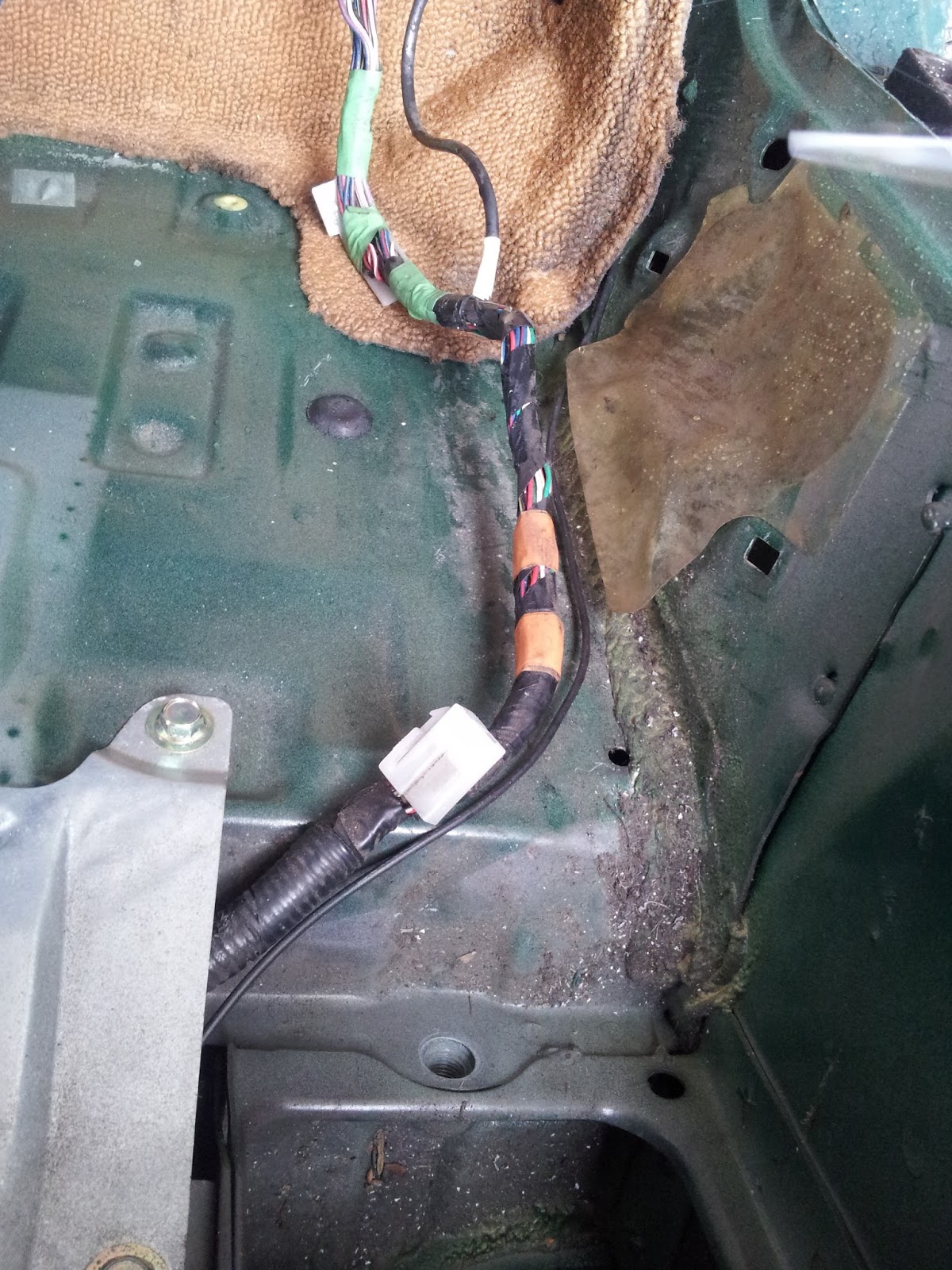
Boot wiring
The boot wiring is relatively simple, everything coming from the same place (well, apart from the fog light wire!);


From the wiring loom outwards, there is;
1. A long reinforced wire for the bootlid brake light
2. Left hand light cluster connector
3. An unknown 2 wire connector
4. Left hand number plate light
5. An unknown 4 wire connector
6. A ground wire
7. Right hand number plate light
8. Right hand light cluster connector
The two other 'white bits' are the chassis fixings rather than connectors. The last black wire on the right is the fog light wire, that is wired up on it's own all the way down the right hand side of the car;
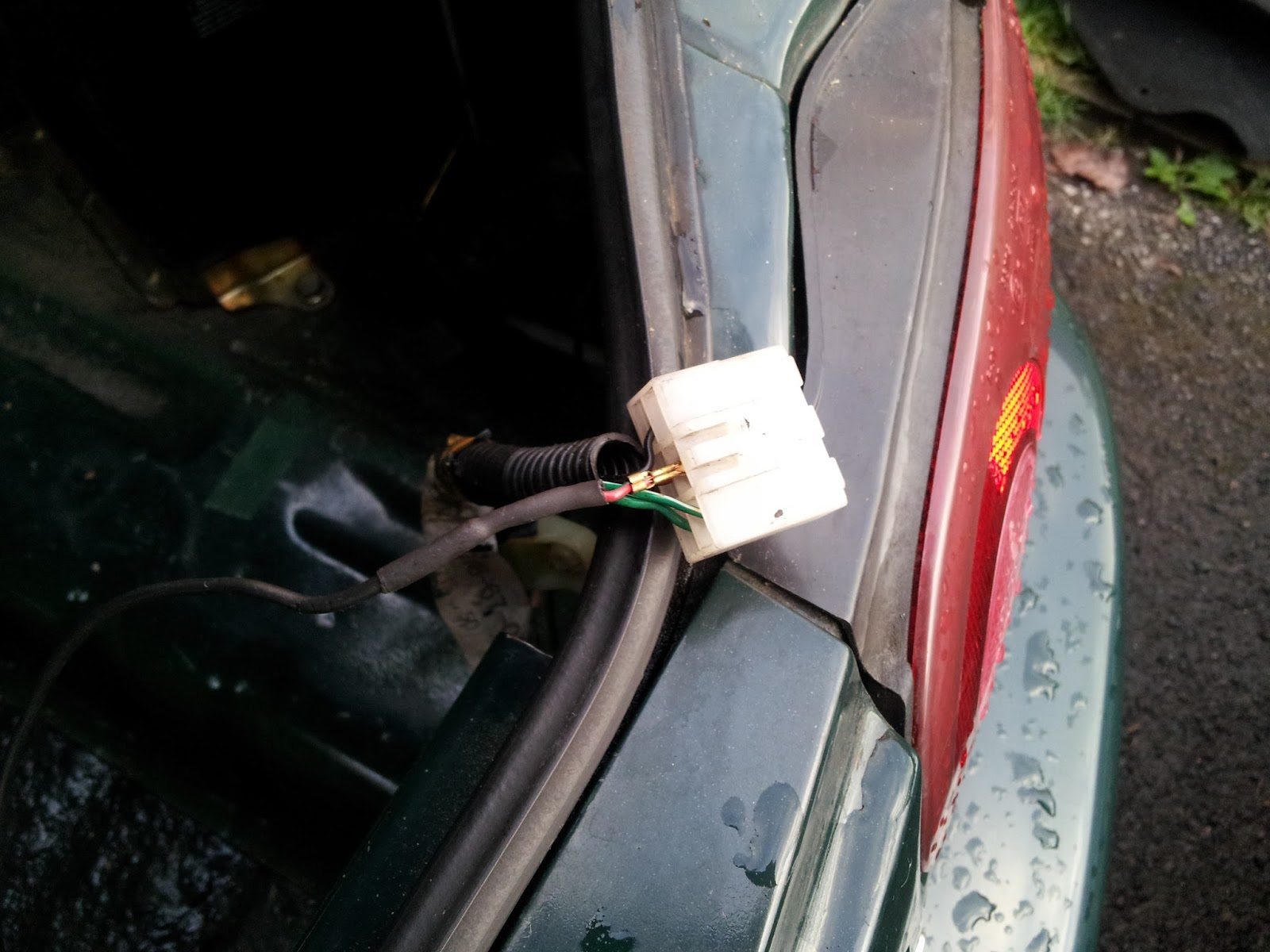
I've removed the fog light wire from the connector so I can withdraw the loom, it might go back in but the cluster fog light is not 'e' marked so I think I'll need to fit a proper fog light.
Sunday 4 August 2013
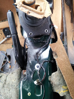
Interior strip part 1 - Wiring
Nothing challenging so far, just a few pictures of the wiring so I know where things have come from;
Drivers side wiring. Bottom left is an unknown connector, from near the seatbelt mounting. The other part of this extension is for the seat speakers, and in the bottom left is the push pin for the door (possibly only for the alarm).

Passenger side wiring. Same again, bottom right is a mysterious unconnected wire from the seatbelt fixing, then the speaker connection. The passenger side also had a separate dust covered connector, I think that is for the rear window demister for glass windows.
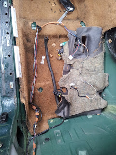
Centre console wiring. Not much here, a connector for the electric windows and just to the side of the gearshift is a light fitting for the ashtray. There is also a push connector for the handbrake, again probably only needed for the alarm. The middle wire still attached to the chassis looks more like a factory fit, but it's not the fog light wire as I found that on the right hand side.
On both sides of the loom, there is a connector for the seat belts. Apparently JDM cars (Japanese Domestic Market, IE Eunos!) have a 'feature'. With the ignition on, there is a solenoid that prevents the seatbelt retracting all the way in. I have to admit, that is quite possibly the dumbest 'feature' ever. A knowledgeable guy over at MX5Nutz suggested the feature could be turned off by removing a fuse. Basically I'm going to remove the wire! The wires down by the seatbelt stalk are similarly useless, so they'll be removed as well.

Looks like the entire loom comes down the drivers side into the boot, then the bits on the passenger side come out of the boot. It's raining at the moment so I didn't have chance to remove that part of the loom, but it would make sense to be the next thing to do.
Drivers side wiring. Bottom left is an unknown connector, from near the seatbelt mounting. The other part of this extension is for the seat speakers, and in the bottom left is the push pin for the door (possibly only for the alarm).


Thursday 1 August 2013
I have a donor!!
Well, I've finally got myself a donor, and a rather nice one to boot. In fact, so nice there was part of me that didn't want to chop it up...

But chopping up will happen, so it's time to start a shopping list. So I will be keeping;
The engine (obviously), gearbox, propshaft, diff, driveshafts, all uprights all brakes, and wheels.
Seats (lovely aged tan leather, should look perfect).
Air vents (chrome surround, the only bit of chrome that I like the look of)
Instruments and switches
Front and rear lights
Full loom and ECU
Pedals with brake cylinder.
Handbrake
I will be selling;
Bumpers (maybe, might be difficult due to the size)
Wing mirrors (£50 average price on Ebay? They're ugly!)
sill covers (nice chrome roadster plates, should get something)
Hood (I was going to try and use it, but it just looks too wide)
Wings, doors and bonnet (again, the size may make it difficult)
Mats (they look really old, but they are v-spec marked so they might have value) Edit: On second thoughts, they won't sell, so bin unfortunately.
I will be binning;
The alarm (blasted thing is a right royal pain in the a$$, and I have a feeling it's going to have damaged the loom unfortunately)
The main body
Boot lid
Carpet (I did think it might sell, but doesn't look like it)
I'll strip the interior first, then work outwards. With any luck I won't have half a car sat on the drive for too long!
I did do a bit of Ebay shopping for things like door cards and stuff, looks like they're a no go on selling so at the very best I'll have to sell the doors as complete and collection only.
Sunday 14 July 2013
MX5 plans
Here are the alterations required to the 'build a car on a budget', so an MX5 can be used as a donor. They were created by Saturn Sports Cars, who don't appear to exist anymore. They were then briefly hosted by Gillham, before they replaced them with another set. Unfortunately, the new set has only half the pages, and is still missing the measurements that this original had.
The document does reference a Saturn Sports cars copyright, but as I have no means of contacting the author I have put them on here with the intention of removing them if requested.
I would strongly recommend you do not treat them as anything more than a guide, and use an amount of common sense when making the alterations. The rest of this blog will contain information on what I am planning to do, so feel free to use the ideas.
And more chassis...
Finished the triangulation now;

I've deliberately left all the rear suspension for now. I've ordered the diff cover from Talon Motorsport, and I'll build the diff cradle and suspension around it.
So the next stage will be the transmission tunnel. The only change will be to open the ends up slightly for the MX5 diff. I can then fit the front suspension brackets and start the wishbones, but I'm hoping that the cover will arrive before then.
I'm going to need to find a new welding helmet though, it didn't go dark during one of the welds last night so I think the auto darkening circuit is failing. Then again, it might just need the glass cleaning/replacing.
Thursday 27 June 2013
Suspension thoughts part 2
As mentioned, the suspension wishbones are going to be all new, mainly to preserve the longer wishbones at the back. So, armed with the Haynes manual, the Saturn modifications and some clever Google searching, I came up with this;
First stage, front wishbones. Looks like Saturn use the same mounting points for the wishbones top and bottom. The front upper and front lower jigs have length dimensions, and the width dimensions are dictated by the brackets and the upright fixings. So I'm happy I have everything I need there.
Rear wishbones. Now these are going to be fun! So as far as I can tell, the Saturn plans don't contain length dimensions for the wishbones, so they're no help. The Haynes plans do contain dimensions but for Sierra based uprights. So a bit of creative thinking is needed. The lower wishbones are quoted to be very similar to the Haynes wishbones,which are 381mm (centre to centre). The wishbones brackets on the chassis are 265.5mm from the centre line. That means the lower outer fixing for the upright is 646.5mm from the centre of the car. I think that is a good starting point, which means I need to make the new wishbone the same dimensions as the Haynes wishbone, but with the layout the same as the Saturn wishbone.
Here is a picture of a rear upright from a mark 1 MX5;

Unfortunately it's from a US site so everything is in inches. Converting to the metric system, the top measurement is 149.225 mm and the bottom is 114.3 mm. In basic terms, it means on the upright side, the top wishbone has got to end approximately 35 mm shorter than the bottom wishbone.
So, back to the Haynes manual. The bottom wishbone mounting point is 265.5 mm from the centre line. The upper wishbone mounting point is 301 mm. So on the chassis side, the top wishbone has got to be 35.5 mm shorter than the bottom wishbone.
This means that the top wishbone has to be overall 70.5mm shorter than the bottom wishbone. With the bottom one being 381mm, that means that the top one needs to be 310.5 mm long. That is 50mm longer than the original Haynes wishbone, but probably double the length of the Saturn wishbone.
Of course, there is the added complication of the rear driveshafts. I already know I need to alter the propshaft, I didn't want to have to adjust the rear driveshafts as well. Maybe I ought to wait for my donor...
The suspension brackets have now arrived, so I can at least get them fitted. Although I still have the whole rear suspension area to fit... and the diagonal bracing... and fully weld the chassis... and do the aussie mods... I'm glad I'm treating this as a fun hobby rather than a career!
Sunday 23 June 2013
Laser alignment
The lack of a build table has worried me from day one. Not enough to sell my motorbike (the chief use of my garage space) but still something I need to sort out. But then I wondered whether there was a way of properly measuring the base. So with the help of an Ebay-special laser pen, I set something up.
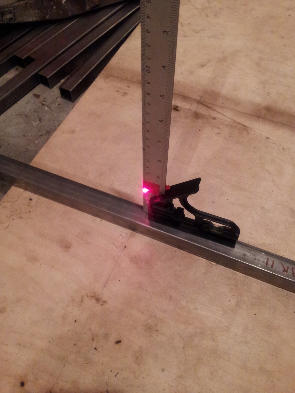
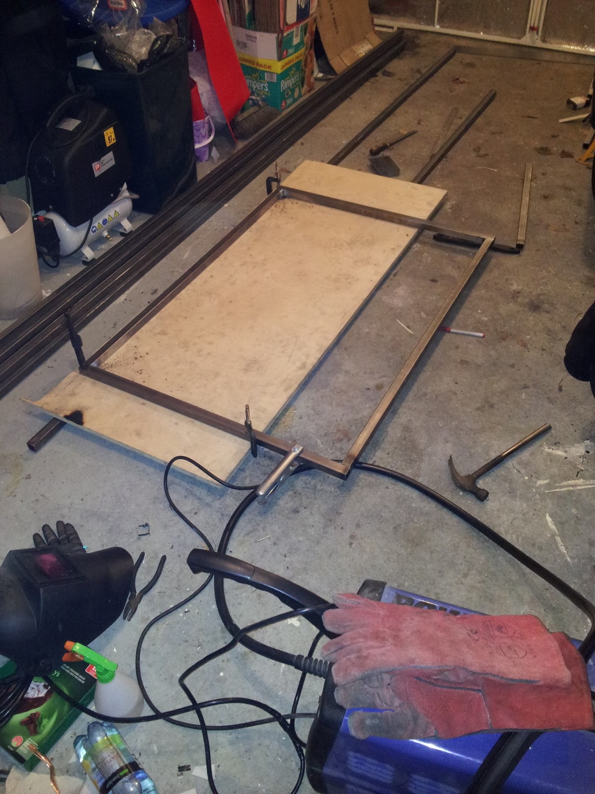
First step, mount the laser;

This is a bit of metal clamped to the front bar, then the laser pen is clamped to the metal. This lifts the laser pen about 50mm off the front bar, and allows me to adjust the pen up and down. It also holds the 'on' button down. I used a combination set square to determine the height;

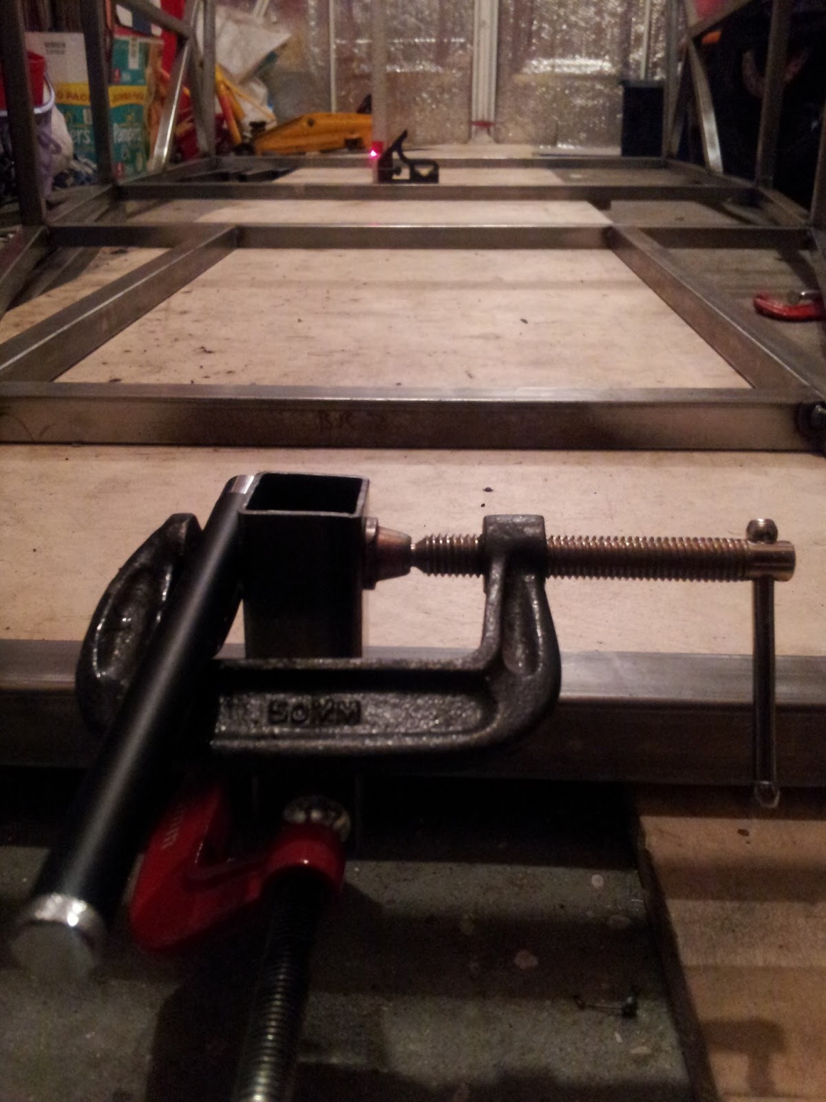
Then used a bit of red tape to mark the laser. I then moved it to the furthest point, and adjusted the laser until the measurement was the same;
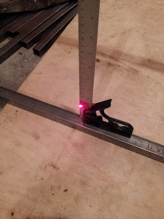
A quick double check that the nearest one was still ok, and I was set. I then used the same measurement on all the other bars to confirm that they were the same height;

And they were! The laser itself wasn't perfect, but focusing on the centre of the laser got me at least to the nearest millimetre.
The next job is to determine whether there is any twist in the chassis. For that I'll use the same technique, but use a lens to spread the laser across a plane rather than just a point.
First step, mount the laser;
This is a bit of metal clamped to the front bar, then the laser pen is clamped to the metal. This lifts the laser pen about 50mm off the front bar, and allows me to adjust the pen up and down. It also holds the 'on' button down. I used a combination set square to determine the height;

A quick double check that the nearest one was still ok, and I was set. I then used the same measurement on all the other bars to confirm that they were the same height;
And they were! The laser itself wasn't perfect, but focusing on the centre of the laser got me at least to the nearest millimetre.
The next job is to determine whether there is any twist in the chassis. For that I'll use the same technique, but use a lens to spread the laser across a plane rather than just a point.
Saturday 22 June 2013
Suspension thoughts
Now that the chassis is actually taking the (sort of) form of a car, it's time to start looking at suspension. So first part was the brackets and the bushes.
The brackets are on their way from Dave at Rogue Engineering, £1.50 per bracket and money for shipping. I did look into possibly making my own (no method of bending unfortunately), or even buying some hollow section steel and cutting a face off, but it would have been a lot more effort for not a lot of saving, so £42 total price for the brackets was the way I went.
Bushes were much easier, another Ebay search revealed a set of 22 crush tubes and 44 bush top hats for £50. Again, as with the brackets, I did look into DIY cheaper options, but the effort and accuracy made this purchase a much better option.
So, on to the suspension wishbones. These are definitely a DIY job, for example Talon Motorsport asks for £300 for a full set of wishbones and I was hoping to build most of the chassis for that! There is also an additional problem...
The Haynes Roadster measurements are based on a Sierra donor, and I don't want that. I decided early on to use a Mazda MX5 as that was a proven alternative with only a few subtle mods. For example, the front wishbones are virtually identical to the Sierra versions, with the main difference being the top ball joint having to be sourced elsewhere. That shouldn't be too difficult, it's either a 3 series BMW ball joint (which one is TBC), or ream out the Mazda upright to suit the Transit van ball joint from the original book. No problem for either of those.
The main problem is the rear suspension. The Mazda alternative is based on the huuuge rear diff cover that the Mazda uses, but it results in the upper wishbones being a significant compromise. And basically, I don't like them. What I'm going for is a replacement diff cover from Talon Motorsport, that fits more like the Sierra diff and allows for 'normal' wishbones and a more standard back end to the chassis. It does appear that I'll be treading new ground though, so I need to do some calculations on how long the wishbones need to be in order to use the Mazda uprights but the 'Sierra' wishbones. Not a huge problem, but it's a task that will need to be completed before I build the wishbones.
I'll also need to understand how Talons diff cover is put together, there are mounting holes but they don't line up with any existing design so that'll be another custom task to do.
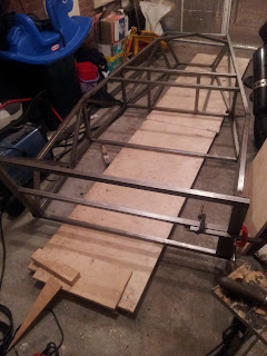
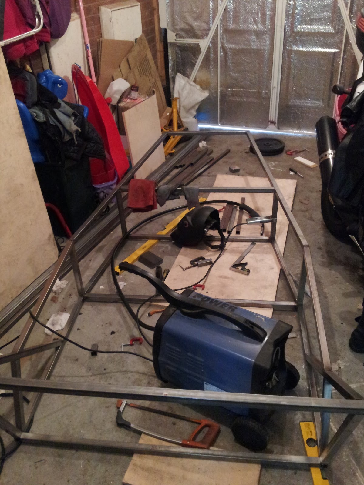
More chassis
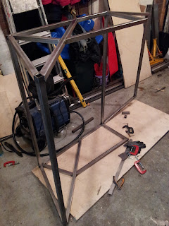
Nothing really new here, just more progress shots;

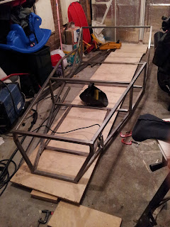
Still looking ok despite not having a solid base to work off. The front end frame sits perfectly without needing to clamp in place, and I only have to cope with a tiny bit of weld induced warping. Before I start adding triangulation I'll use a laser pointer to confirm the base is perfectly in line. More on that later.


Tuesday 18 June 2013
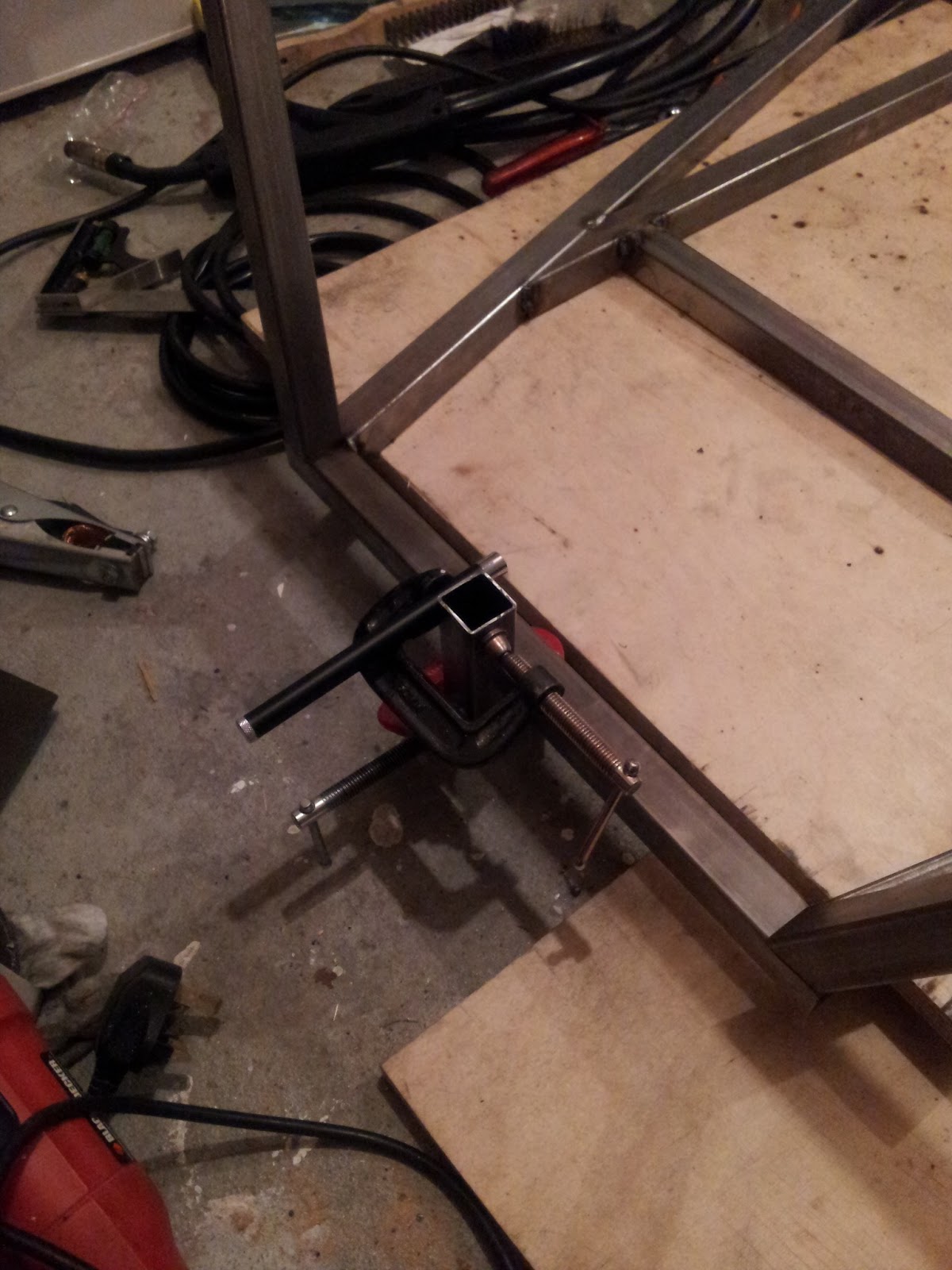
Space invaders
Courtesy of a Facebook friend, this section is entitled 'space invaders'. All will become apparent with these pictures;

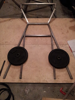
This is actually the build of the bottom section of the engine bay, but I do suspect that if I lined up lots of them in a row, I would have to fight the urge to hide behind a brick wall and throw single rocks at them...


Monday 17 June 2013
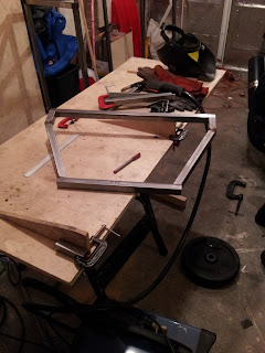
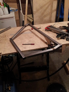
Front of the chassis
Now here is where the problems started. Remember the wooden model I'd made earlier? This is where it went a bit wrong. Turns out the Haynes roadster book has some errors, some of which I knew about but didn't realise I'd come across one so early in the build. I cut the metal, then found the uprights of the front section were way too short! They went into the spare metal bin...
The reason why the wooden model worked fine was simple. The Haynes measurement shows an overall measurement for the bent metal, and measurements for the two halves. The overall measurement was the wrong one, but because wood doesn't bend I'd used the two half measurements. So the model worked out fine, but the real one failed.
While I was having a little rant on locostbuilders, a considerate builder posted some further details on how to build the front, not only to compensate for the measurements being wrong but to save future problems with the suspension mounts. So instead of the two uprights being partly cut and bent, they were completely cut and welded with a 'twist' in. The twist was measured against the jib so that when the front is welded in place, the vertical pieces are perfectly in line with the other uprights for the suspension.
In short, this is what I ended up with;


Very happy with this now it's finished (and the uprights are long enough!).
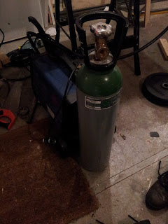
At the same time, I picked up my welding gas;

OK, not a very exciting picture, but I couldn't resist! I've also ordered a side mounting argon valve from weldequip, as soon as that arrives I'll get things plugged up.
Sunday 9 June 2013
Next stage of the chassis

My garage doesn't actually have enough room to build the full wooden base for the frame, I know it's going to bite me at some point but so far it seems ok.
Gasless MIG welding is horrible by the way, it was at this point I started to look at some gas. A quick check on Ebay found me an Adams gas supplier in Telford. £55 returnable deposit on the bottle and £30 for the argon mix gas should work quite well.
Thursday 7 February 2013
Total costs....
This will be updated as I go, to keep track on what I spend on the car.
£97.56. First lot of steel for the chassis, from Camp Steel.
£42.00. Suspension brackets from Ebay - Daveo1211.
£56.45. Bushes and crush tubes from Ebay - shmason2011.
£440. Donor MX5.
£50.44. Steel tube for suspension.
Total as of 04/09/2013. £686.45.
Other costs (not car parts but used to build the car).
£85.00. Argon gas (£55 will be returned deposit at the end of the job).
£137.99. 1 tonne engine crane (hoping to recover at least half of that by selling the crane after I'm done with it).
£13. Welding wire (this won't be the last one!)
£8. Socket for the rear hubs.
£40. Delivery of above mentioned MX5.
New section, sales!!
£50 wing mirrors.
£50 soft top.
First post
Time to get documenting methinks! I've been building my car now for many months, but actual work time maybe only a couple of days. I'd like to blame a busy social life, but it's more to do with parenting duties...
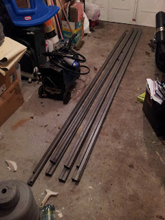 First purchase, chassis metal. Purchased from Camp Steel, in the centre of Birmingham. Nick Brown was good enough to cut them to lengths suitable to fit in my car, and also let me have a rummage in the scrap bin for some odds and sods. I saw a lot of plate steel that will work well for later stages of the build, but for now I've just got some 2mm for welding practise. I'll have to see whether he does the scrap on a per kilo basis or whether I could make some similar arrangement.
Prices at this time were;
1" x 1" x 1.6mm ERW Tube x 6.1 M £10.90 each +VAT
3/4" x 3/4" x 1.6 ERW Tube x 6.1 M £7.95 each +VAT
I have 6 lengths of 1", 2 of 3/4". They were all cut in half for transport.
First attempts with the hacksaw showed that a) my cutting skills are in need of improvement, and b) it's going to take a while...
10/02/2013. John off Locostbuilders was kind enough to provide me with lots of pieces of plate steel ready cut. £25 later and I have nearly all the pieces I'm going to need, I reckon maybe an A4 piece of 3mm steel will be enough to cover the rest. The diff mounting should be interesting though, I'm hoping to take advantage of a new casing which will use the Ford diff mounting brackets. I don't like the MX5 diff mounted as a whole, it seems to be a bit of a 'bodge' in my opinion.


So, this is how it started, way back in February...

Prices at this time were;
1" x 1" x 1.6mm ERW Tube x 6.1 M £10.90 each +VAT
3/4" x 3/4" x 1.6 ERW Tube x 6.1 M £7.95 each +VAT
I have 6 lengths of 1", 2 of 3/4". They were all cut in half for transport.
First attempts with the hacksaw showed that a) my cutting skills are in need of improvement, and b) it's going to take a while...
10/02/2013. John off Locostbuilders was kind enough to provide me with lots of pieces of plate steel ready cut. £25 later and I have nearly all the pieces I'm going to need, I reckon maybe an A4 piece of 3mm steel will be enough to cover the rest. The diff mounting should be interesting though, I'm hoping to take advantage of a new casing which will use the Ford diff mounting brackets. I don't like the MX5 diff mounted as a whole, it seems to be a bit of a 'bodge' in my opinion.

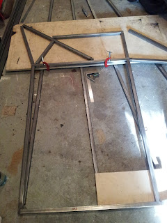
First segment completed. A while back I had completed a one fifth scale wooden model to see if there were any issues with the plans, turns out it did miss something (more on that later).
Next job, cockpit frame;


So that was February....
Subscribe to:
Posts (Atom)