The rear mount will be a lot easier than the fronts. It's basically taking the place of an existing bracket that bolts to the bottom of the gearshift mount. A plate will be made that does the same thing, but instead of mating with metal, it'll go via a Landrover rubber mount that I've bought.
This is the existing bracket in place;
The two bolts at the top will be reused, the one at the bottom will not as it was actually hitting the chassis where it is at the moment.
This picture shows a measurement with the bracket removed;
I'll be working on a 58mm distance between the face of the bolt holes and the chassis bar. The reason I took the bracket off here was not just because it made it easier to measure, but because the bracket forced the engine crooked. The two holes are in fact central to the gearbox.The bolts to the engine appear to be M12, but I don't remember them being very long. 40mm between centres (typical metric Mazda!!), 3mm plate. This is the view from above;
From the bracket, this bolt hole is in line with the other two, and here I'm showing that it's interfering directly with the crossbar.
The rubber mount isn't complex. It's 38mm tall (rubber part), 77mm wide. Each fixed bolt is 20mm long, M10 fixing. That means a 78mm tall mount. If I use 3mm plate in front of the cross member, I have 58mm left of the mount to fit in a 58mm gap. That's a bit of a coincidence.
So time for a bit of designing...
An Austin Healey lookalike, using an MK HSR body on a Haynes Roadster chassis and an MX5 donor.
Sunday 21 June 2020
engine mount progress 2
Only a short update as the previous one contained the main information. Here's the engine mounts mostly welded;
I'm not overly happy with the inside welding, but it's strong enough. The outside welding is a bit prettier, probably because it was just an easier angle to work with!!
The dishes are just tacked on for now, my gas gauge is basically reading zero now although there is still gas pressure. I might try it tomorrow, but I also need to contact the Adams gas supplier to get a full bottle.
On to the front engine mount now, time to study the photos I made when I had the engine in place. It should be a fair bit easier to do, just two plates with the landrover mount in between them.
Monday 15 June 2020
Engine mount progress
Well, I managed to get to a point where I can get some metal cut. I still don't know whether I'll be able to get some welding gas, so there is a good chance I'll get halfway through this job and have to stop again.
At least for now I've got things started on the front engine mounts. I stuck to the design I had put together in Fusion 360, and the 3d print has been extremely useful. Especially as it's exactly 50% of the original, I can actually use it for measurements.
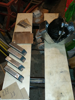
So here are all the bars, plates and fillets cut and mostly shaped;
The two bars are the front have been shaped to fit the engine mount which is a rectangular bowl shape. The two plates are 3mm steel, as are the four fillets.
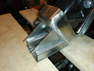
For measuring I bolted the two engine mounts together (top right). This meant that I could position the weldable part at the right angle for both sides. So far I've been cutting against one side and measuring against the other, and it looks pretty good. The engine mounts will go together like this;
The shaping of the bar ends is a bit clearer here. Then they fit to the mount like this;
The whole plate + bar + fillet goes up about an inch or so, so the build will be much more central to the mount dish. It also allows the engine to sit lower in the chassis. I can't show that here because it's all flat on the workbench.
Oh yeah, the workbench.... new surface, courtesy of some very generous wood donation. It's tougher than the MDF that came on the bench before so should be a nice work surface for a while. Of course, it shows the weakness in the workbench metal, but hey I can't have everything!!
So a bit more profiling for the second pair of bars, a trim of the fillets then weld them all together. Then on to the gearbox mount (which is basically just a plate although I'll do some reinforcement there).
Subscribe to:
Posts (Atom)


