Friday 9 July 2021

New seats

 On to the new seats. As mentioned before I'm making a frame, that will then be filled in with plywood and surfaced with foam before the leather goes back on. First thing, another delivery from the Metal Store;


I highly recommend the metal store, it's just convenient compared to local stockholders. The prices are a bit more, and you have to make sure to get it above the minimum postage limit, but that doesn't take much.

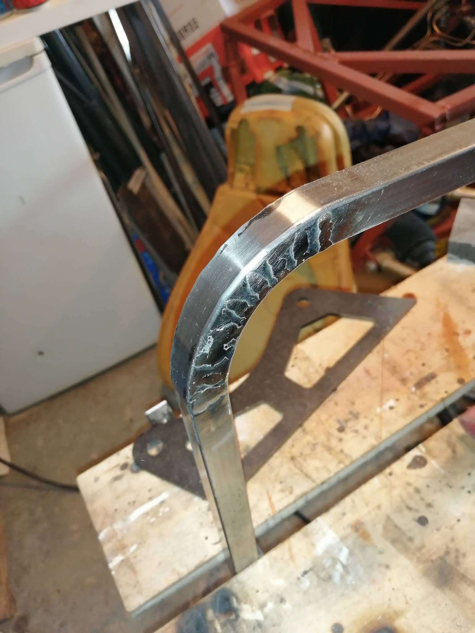
First thing is that I wanted to bend the corners. After many webpages and youtube videos, I decided that it wasn't going to just 'bend'. So I went back to my 'segment' approach. Basically cut slots on the inner side of the bend, bend the metal and weld it up.

This is after a cut, bend and tack;


This worked really well, although I had to go a bit deeper with the angle grinder as the first attempt couldn't bend round to 90 degrees.

After welding (and a fair bit of blow through!) and clean up I had this;


I then continued with the others, and of course they went much better the second time (and the third and fourth time);


So these are now ready to be welded up. 

Next part was the head rest. This is the hardest bit as it's a full 180 degree turn in a fairly small area. First, the wood template;


This takes the outline of the leather seat, note that it's not symmetrical. The Mazda seats actually lean into the centre, presumably to take into account the roof. I'll be doing the same with mine.

Next was to find the cut positions. Each cut is 12.5 degrees, so there's sixteen cuts to do. And because it's not a perfect semicircle, I had no chance of drawing it by hand. Therefore I scanned the above picture into the computer and overlaid it with segments at the relevant angles;


This gave a good match to the outline, and as you can see the sections are very different lengths. At the 2 o'clock position there's two cuts that are only 2mm apart, this is to get the correct curve.

Once that had been designed and printed out, I could then follow the same process and cut the slots to make the curves;


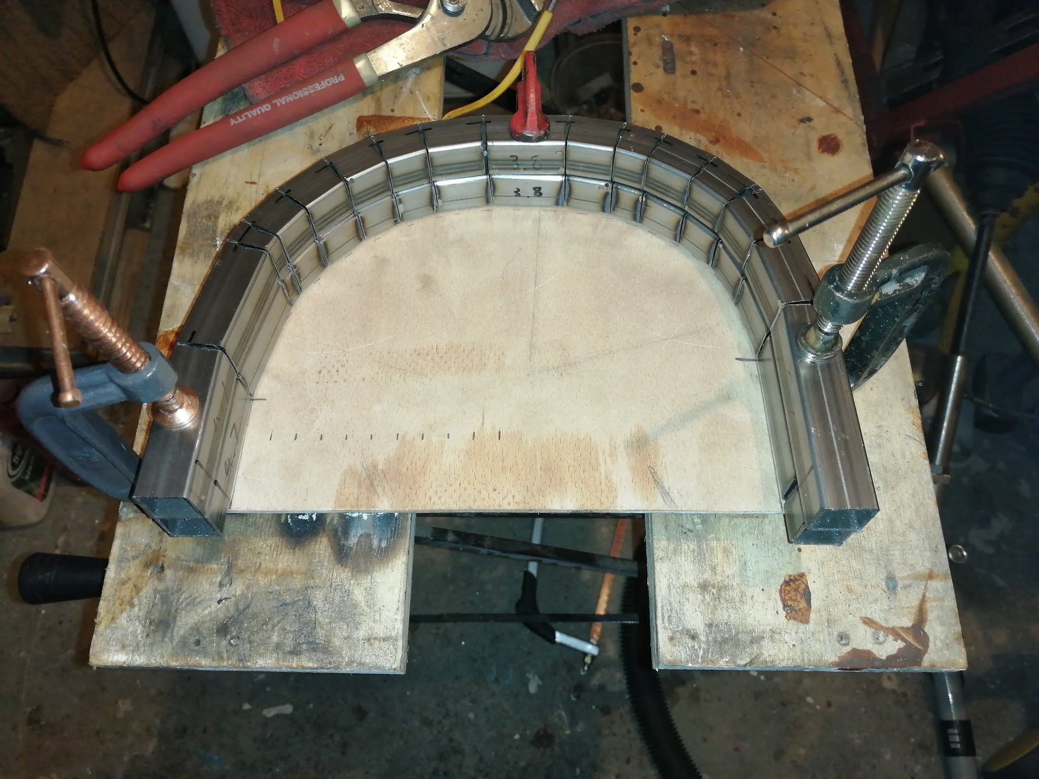
Overall I'm happy with how they've come out. Some of the gaps are bigger than others but as long as I'm careful with the tacks then it'll work out fine. Obviously they're overlaid against each other above, in the car one will be flipped to get the balance.

This all took around three evenings, and I was really tired by the end of it, so I've not made any further progress. Having said that, it's only the seat-back sides that are required now, which are much shallower angles. I think I can achieve the sides with only one or two cuts, which is a whole lot easier.

Then it'll be drawing the outline on the plywood and cutting the pieces out. Once that's done and mounted I can then add foam. 

I do need to work out the seat runners. For IVA I want to put the seats quite low to avoid the seatbelt, so I'm having the seats fixed for the time being. But the bars in the chassis were for the MX5 adjustable runners, so more metal is needed. And more fixing. Not a big problem though.

Saturday 26 June 2021

To sit or not to sit

 I've still got a fair bit to do, but a big chunk that can be done next is the seats themselves. I've already got the fixing points for the runners, so I had it all planned to reuse the donor seats. A while back I dismantled a seat base and it came apart as a metal shell, a sponge block and the leather skin. This looked good, modifying the metal base and reducing the foam would work. Unfortunately, today changed that plan...

It turns out the seat back isn't as substantial as the base. It's basically an upright mattress, a series of horizontal springs coated in foam with the leather on top. So dismantling it just means I'd end up with a pile of springs and bits of foam that used to be a chair back.

As you can imagine I'm a bit frustrated. I now need to come up with another solution for the seats. However, this could be a good thing. Mainly because I can get things working better for IVA.

The plan now will be to make a metal frame that matches the existing leather skin, with either plywood or metal to fill the gaps. Then new foam to rebuild the seat, then reuse the leather. Sounds fairly simple. I've made a template for the seat back, I'll do the same for the base. Then maybe some thin ply to test fit everything, or even as a permanent solution if the metal frame is solid enough.

Time for more metal though. The stuff I have is too thick for a seat, both in terms of diameter and gauge. I don't want to use metal that can support a fibreglass body, just to hold up a bit of sponge! So I need to work out how much each seat will use, as well as future proofing anything else I might need. Measuring the seat I can see the back is 800 x 400. Assuming that it just needs a single loop on the outside, that's 

    800 + 800 + 400 + 400 (x2 seats) = 4800 mm

Metalstore have 1.2mm gauge x 3 metre x 19mm for £12.78 a length. Two of those should be fine for the seats.

I can also get the metal for the outriggers. With the back panel being 1.5m x 2.5m, I could assume that it basically needs a complete circle of metal for supports. That is 1.5 + 1.5 + 2.5 + 2.5 so an extra 8 metres.

All this is quite fortunate of course, because metalstore have a minimum £50 excl VAT order for free delivery. 5 lengths should do it, and that also works well with the seat metal. 

I could also do with some tube for fixing holes. Just some half inch will do here, 1.2mm again to weld easy. 

Handbrake cables and fitting

 Well, last weekend was a bust due to much higher priorities (more on that later), but hopefully today I'll be able to get started on the handbrake cables. 

The first thing I want to consider is how tight the curve can be on the rear cables. On my car I've mounted the calipers backwards, so instead of routing the cable directly forwards, mine have to loop round. I also have the 'option' of mounting the calipers upside down. While this does cause headaches for bleeding, it may also help the routing of the cables. Whichever way round the brake flexi will always go up, which is easy. The handbrake cable has a mounting bracket that changes the angle depending on orientiation.

I guess the first thing I need to do is try both ways up and see which one gives me the best cable routing without rubbing on the chassis. Then the next question is how tight those cables can bend. This picture suggests they can bend quite sharply;


This appears to be a complete U turn in the length of the lower wishbones, using the standard bracket to fix it on the diff bracket. This would probably be tighter than I need it, but it does mean I have a fair bit of flexibility in the mount. 

The first step is now done. I've replaced the angle fixing brackets that were on the cables with straight brackets, and welded corresponding brackets to the chassis just behind the diff. The cables will route from there to the transmission tunnel, where they will fix into a mounting plate. That's the next step, to create a mounting plate across the tunnel. The cables are intended to clip very similar to flexi pipes, so I've ordered a couple more spring clips. Hopefully I'll get to cutting the brackets once the first step has cooled down.


(Several days later...)

The rest of the handbrake wasn't too painful in the end. Apart from a full week of trying to order some handbrake cable (how can any seller think bungee cord is the same as handbrake cable?!!), I finally managed to figure out the other end. First, a trial fit;


This bracket was the first design, but the handbrake cables are existing too high and rubbing against the chassis. This had to be dropped an inch, to this;


This is the final fit, all welded up with the balance bar in place. This will work fine, so the next part is the front section. It needs to be adjustable, so I spent a while figuring out how to drill through a threaded rod to get this;


Along with a cable clamp at the end, and a nut on the thread, this is my adjustment mechanism;


But at this point it occurred to me that I need the bodywork in place to figure out where the handbrake can go. There's a few places for it to go but it needs to be usable. So for now this is the end of the handbrake. Given that it's two holes and two bolts to fix it in place it shouldn't be too much work.

Next job, seats...


Monday 10 May 2021

Rear pipes done

The rear pipes were a bit easier. The only worrying bit was the first bit, if I had got that wrong I wouldn't have had enough to finish the job. Fortunately I just worked smoothly from front to back. This is the front part with the clutch cylinder and steering column in place.


The brackets down the transmission tunnel did their job, it made it easy to secure things in place.


And the rear pipes were really easy, very short and only the frame to avoid. They weren't even long enough to warrant fixing, but I added one to the left hand side just in case.

Talking of fixings, I think I need to add a couple more where the rear pipe goes vertical against the firewall. It can move up and down at the moment which won't go down well with the inspector. I just need to add ones on the bends to make sure.

Next job is the handbrake. The two rear cables come from the calipers and head towards the tunnel. I need to change the fixing brackets on both of those to bolt them to the chassis. They'll then come together into the balance bar which needs mounting in the tunnel. It'll need extending all the way down the tunnel to some sort of mechanism to turn it round into the handbrake. Sounds relatively simple as long as I do each section in turn.


Saturday 8 May 2021

Front pipes done

 Now I had an idea of what flares I need for the pipe, I could make a start. And it's gone really well if I say so myself...


The brackets worked really well, and once everything had been tightened the pipes are absolutely solid. I'm tempted to add some brackets between the pipes, and maybe wrap the pipes with tape where they sit inside the brackets. There's enough of a gap between the pipes and the chassis. Unfortunately the steering column had other ideas, so I had to do this;


This gives an inch or so all round the steering column. So it's on to the rears next. 

Just one last point before I head back into the garage. Everything I've done on the car has been done in segments, then I take the parts off and store them. This means that 'conflicts' such as the column above are very likely. Just off the top of my head I'm thinking the diff and the fuel tank will have fixings that need to occupy the same point in space and time.

If I had built everything on the chassis and left it there it would avoid conflicts, but the work would have been a great deal harder. I guess I've made the right call to do things in parts, I just need to manage the conflict as it arises. Oh no, I sound like middle management...


Tuesday 4 May 2021

Brake pipes

Wow, this was a long time coming... so, on to brake pipes!!


This started well, the balance valve sits quite nicely alongside the master cylinder and is away from anything sensitive. Apart from the pipe bends being tighter than the flaring tool could handle, it was pretty easy to fit these two.

It was the next pipes that were confusing me. The ones above were double flared, a 'female' type pipe ending. But looking at my flexi pipes I could see that these were also female;


I initially thought that I'd gone wrong, so on to the trusted internet I went. There was lots of toing and froing, but eventually I found a 'bubble' flare;


This particular one was made using the AB tools flaring tool. By the way, I can heartily recommend their flaring tool, it does a great job and is very quick. 

So now it's onwards with the rest of the pipes. I'll be clipping them in at appropriate places, running them as required. The small pipes were a confidence boost, I think the longer runs should be a piece of cake. I just need to weld on some support tabs while I go, this isn't an issue as I've already done several long runs. 

I remember a story a while back about people who work on half-completed builds, they said that the chassis welding was often 'ok', but the pipes were done when the enthusiasm was there and so they are generally done to a very high standard. Wiring was the main thing that half-completed kits had trouble with. Fortunately I seem to have done things backwards, I got the wiring looms tidied up before I did the brake pipes! 

Sunday 21 February 2021

New plan for panel edges

 So after a few weeks of ridiculously low temperatures and 'other jobs', I finally got back in the garage. A quick tidy up, and I could have another go at panel trimming. It did not go well...

It's basically a lack of consistency. To get the same cut all the way along all the panels would need some kind of miracle. So I'm not going to attempt it. I'm going back to the original plan of using edging trim. 

I'm aiming for some padded trim, maybe thin neoprene or similar. It needs to go over the rivets, either using cutouts or thick enough to hide them.

Anyway, that's one job ticked off. Well, one job solved, not necessarily completed. Back to the brake pipes now. I have the new brackets drilled, I have them in the right position so I'll get them welded up. Then the solid pipes can start getting routed, and the handbrake cable can be worked on.

(Small update). OK, the tabs are now welded up, one of those jobs that I would put off over and over and just not get anywhere. I'm impressed with the welder that it just fired up and welded smoothly. Next step, brake pipe location. 

Sunday 10 January 2021

Some small jobs completed

It's been a little cold recently so my plans of getting an hour each day in the garage for either tinkering or exercise has turned into video game time for the most part. I've not got much done on the car but I have completed all the Uncharted games and about to finish the last Tomb Raider. Time well spent? No idea!!

Anyway, there has been a little bit of work done. First for the brake pipes, I've got a position for all the flexi pipes and now just need a bit of time and space in the garage to weld them in place. I also got the front handbrake cable to see how that will work. It's short, but that's expected. At least it contains the balance bar that is needed to connect it to the rear cables. I'll have a go at extending it then I can start on mounting the handbrake itself. 

The grub screws for the suspension arrived... and they're wrong. I should have realised the thread was too coarse to be regular M6 x 1.0. It's closer to 1.25. And of course, I can't get M6 x 1.25. A quick discussion on locostbuilders pointed out that an imperial screw would be better, so I've ordered the closest match. I'll try them when they arrive.

And lastly I finally managed to have a go at the panel trimming. The idea was to use a handheld router to cut a rounded edge in the aluminium. I managed to give it a go, and the results are pretty decent. I need to refine the process because I was using a wooden edge template. By the third cut it was no longer straight. I need to put together a metal former that I can bolt the panel to before I cut it. I want to practice as much as possible though, especially on the long runs. It looks really good over a couple of inches, and the join between panels is immaculate. But can I realistically maintain it over a couple of feet?

It did occur to me that it doesn't need to be on all panels or on all edges. In fact, it's probably only going to be the transmission tunnel edge. Even the side panels are either going on the outside or will have the fibreglass panel overlapping on the edge. 

(pictures to follow when I find my USB cable, it got 'tidied' along with the Christmas decorations...)

Sunday 3 January 2021

Brake pipe mounting part 1

 The flexi's have been positioned and I can now weld the tabs on (more on that later). Now I need to route the brake pipes. While I have the end points, I don't have the start points because the proportioning valve isn't mounted. Here is how it looks on the original car;


The valve needs to be on the other side though. Time to line things up and see how it goes...