Sunday 26 May 2019

Back panel change of approach

As you can see in the previous post, I changed my mind about the back panel. The way I'd done the tabs on the edges was only possible if you can manipulate aluminium like paper. As this is impossible in the real world, I've had to redesign what panels go where. Here is the middle back panel as it is now;


I've split off the side parts to make them up as separate panels. This changes a few things;

1. The transfer from back panel to transmission tunnel is now a fold rather than a seam, I think that will look really good.
2. The two side parts can extend on to the panels either side to provide a secure fixing. The transmissions sides and the car sides can then fold in front of them.
3. There will be a seam on the diagonal portion. As this is partly hidden by the back of the seats I'm not overly bothered, I've also positioned the middle panel rivets to allow the side panels to fit in the same place. The panel isn't trimmed to the centre yet but that can be done once I've got the side panels sorted.

Since all four side panels will rely on the back panels being in place, they're the next things to be done. But first... I need to grind down the stitch welds so I have a flat surface, there's no way a panel will sit flat on those lumps!!

Oh, here's the two panels ready to go;


And with the middle panel in place;


Assuming the arrows are referring to the grain of the aluminium, I'm intrigued as to how it will look.

Two down...

The first couple of panels are done, admittedly they're the easy ones that just go on the top.


The process was similar to the floor panels, but I had to be careful with the edges as they're visible. Actually, everything is visible so I had to be careful all over!

I started each panel on an edge and made sure there was enough metal to cover the relevant hole. I drilled a couple of holes for some Cleco's to hold the panel in place, then marked the fold lines. Using my DIY folder (which actually does work on aluminium a lot better than the thinner steel) I put the relevant folds in the panel. Then using Cleco's as I went, drilling and fixing the panel.

The last stage was to trim the panels to size, the power file came in very useful here. I brought each panel flush to the steel, whether I'll regret that decision or not only time will tell.

There is just one panel left for the transmission tunnel top, but that will use rivnuts for fixings. I think I'll start the process the same as the other panels, the rivnuts will use similar if not slightly larger holes.

Next ones are the sides, and I'm not looking forward to those. Folds, cutouts, all manner of unpleasantness. All so I can have a smooth interior, I hope it's worth it!

Sunday 12 May 2019

Panel tetris

So here is the main aluminium panel, with all the pieces attached;


As you can see, it was a bit tight to get all the panels on. There are a few things to note here. First off, I've not left myself much waste between panels, so I'm hoping the cuts will be pretty accurate. I'm also doing something a bit unusual with the back panel. Rather than trying to do it in one large panel (which wouldn't have worked due to the way I've left tags on the panels for fitting), I've split it into three. The two panels near the centre are intended to go behind the passenger and driver, and form the bulk of the panel. The T shape part towards the right is then the middle panel and the first part of the transmission tunnel. I've done it this way so I have quite a clean rear panel between the seats, with adequate room and access for riveting. Bringing it down on the tunnel also allows for a clean transition between the two, without the need for welding a fixing bracket in place.

This will use all of the aluminium I have left, so if I go wrong I've got to buy more. Which won't be cheap, while the panels themselves aren't too bad it's actually getting them home that's the issue. And I've found that most metal suppliers don't work weekends, so it's a case of having to go during work hours.

OT - MIG welder earth lead

Time to go off on a little tangent here. For a while now my welding has been a little 'rough', and as the saying goes 'a poor workman always blames his tools'. However I think in my case it is actually the tool!

My current welder is a Clarke MIG welder, I got it cheap off Gumtree from a place that was upgrading. It was a little rough, but after a clean it seemed to work well, and better than the old Wolf Aldi one that I was working with.

It's always lacked a little 'something' though, so it was time it got a bit of TLC. First off was the liner. It was a steel one originally, but I get the impression it was way past it's use by date. Me being a cheapskate that I am, I bought some net curtain wire for a pound!! It made a huge difference though, even feeding in the wire for the first time I could feel it moving so much easier. It also meant I could turn down the wire tension and the feed speed, which I always felt was higher than it should have needed to be.

The next job was the earth lead. It was definitely something that had never been replaced, and it never felt good with the way it could bend really easily at certain points. I reckon there were several weak points where some of the internals had broken. The clamp itself was also a cheap one, and I frequently found myself with arc points on the clamp where it hadn't quite contacted properly and made it's own weld.

Looking on the internet it seemed the done thing was to replace it with a Dinse connector and upgrade the lead. So that's what I did! In hindsight I should have taken more pictures, but here's the first. It's the offcuts of sleeve, showing the difference between the old wire (right) and the new (left);


Considering it's a 150A welder, and the new wire is rated to 200A, I have no idea what the old wire was even doing there!!

The main challenge with this was that it was crimped directly to the copper winding on the transformer inside the welder. What I did was cut the old cable off about an inch away from the crimp, then open up the copper wires. Once I'd done the same with a length of new wire, I slid them inside each other then soaked the whole thing in solder to give it as good a connection as I could make. Two layers of heat shrink sleeving and the original woven protector over the joint and I was happy with the result.

The next stage was to fix the Dinse connector to the case. This worked surprisingly well, with nice big screw clamps for the wires. I'd bought a pack of five terminals all rated at 200A, and it was just a case of screwing everything down. This is the outside of the case now;


It even fitted in the same location as the old grommet, right down to the keyway that stops it rotating as the cable is clamped on.

The last stage was to make up the cable. So dinse plug on one end, and the new earth clamp on the other. It really was that easy. This is the new earth clamp now;

This is showing one of the terminal connectors that I had, it's quite clear how chunky they are.

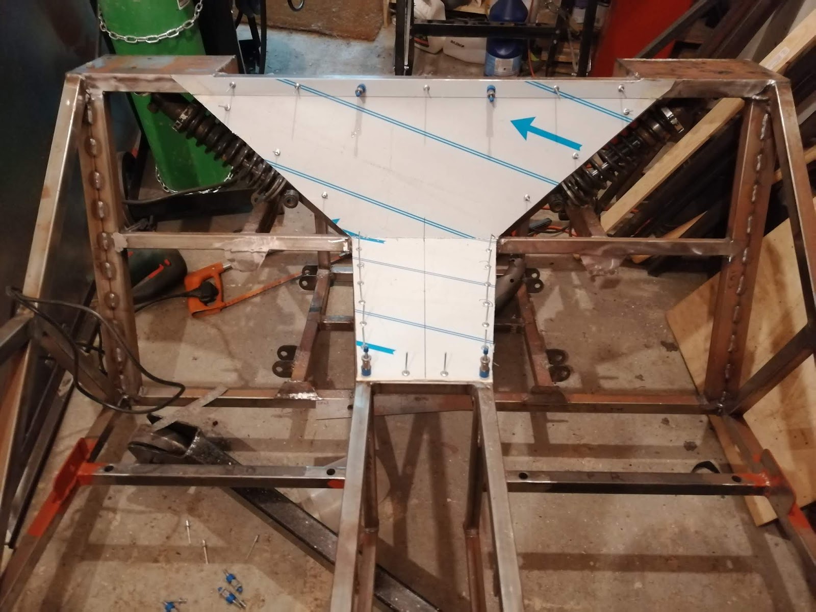
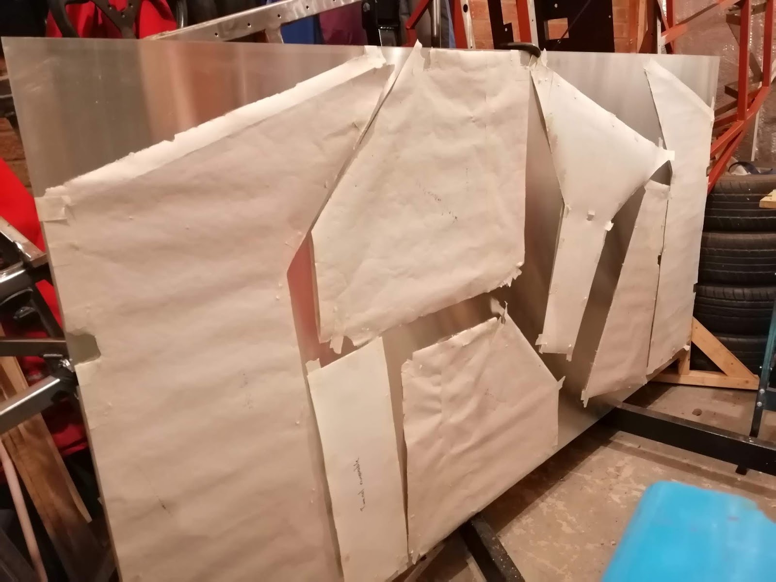
And that's it. Of course, at the moment I'm making body panels out of aluminium, so there isn't much welding to be done. Still, I'm looking forward to giving it a go.