Sunday 21 September 2014

Upper rear wishbones

I've been scratching my head with this one for a while now, and have come up with three designs, based on the following diagram;


The top blue box is the coilover bush and crush tubes, the lower one is the top mount for the MX5 upright, and the green is 5mm plate steel.

Design 1 (left) is the smallest design, but it leaves the coilover acting on the M10 bolt running through it, with potentially bending forces rather than sheer forces. However, this is how the Westfield mounting is done, albeit potentially with more than just an M10 bolt.

Design 2 (middle) gives more support through both, but again I wonder whether the combination of the upper mount and the coilover put the bolt in a bending position.

Design 3(right) is the belt and braces, this was my original design. No bending forces, all sheer forces. But is it too much.

Turns out that Westfield actually use two designs, one that is close to the first one;


And another that looks the same as number three;


To be honest, I think I'm leaning towards number three...

Sunday 20 July 2014

Measuring up the lower wishbones

First step, measuring the length of the rear lower wishbones. A fairly simple process, let the uprights stand vertical, the CV joints sit comfortable (not under tension or compression), then measure from the centre of the bottom fixing to the centre of the wishbone bracket;
And the magic number is 375. So I can compare that to an existing Saturn design;
That shows 395.8 from edge to edge. With a wishbone tube being 33.7mm wide, that means mine are longer at 408.7 from edge to edge. Unfortunately trying to get it down to 395.8 seems to compress the cv joint a bit more than I'd like (and as the suspension moves it will compress even more). I repeated the process on the other side, it actually sits 5mm shorter, but any reasonable amount of camber and the driveshaft binds on the diff.

I also measured up the metal. I have 2490 of tube, and based on the 375mm length, I need 2420 of metal! So no room for mistakes! I'll be using 19mm for the top wishbone, same as the Sierra design. This is because the suspension mount isn't on the wishbone. I'll still brace it a little bit, but at least I won't need the thicker tube.

Saturday 19 July 2014

Driveshafts and uprights

The diff is in place, and the driveshafts, and the uprights. And now I have a problem...

I had planned to fix the coilover alongside the upper fixing of the upright, like the Westfields do;

But with the coilovers at maximum extension (13 inches) the driveshafts are horizontal. Which means as the suspension compresses, the driveshafts will be angled upwards. I don't think this is a good thing. Even comparing to the picture above, I would more expect the driveshafts to be horizontal under full load.

So time for yet another rethink. I may try and mount the coilover top near to the edge, but that would need some reinforcement on the plate.

Mmm, I've just noticed, the uprights are backwards in the Westfield...that could be useful...

(Later that night...)

I've also just noticed that the upper mounts on the Westfield aren't mounted to the upper plates, they're mounted to the cross member. The hole for putting the bolt in is actually in the back seat panel. The plate is only used for the rollbar. So I'm thinking, if I reverse the uprights, mount the coilover as per Westfield, it would be mounted an inch or so down and out so the shorter shock wouldn't matter anymore. There's a little bit of bracing added, I can do the same.

Looks like I have a few things to try out tomorrow! :)

More diff...

I treated myself to some new welding gloves, mainly because the right index finger was so burnt it bent sideways instead of inline with the knuckle... anyway, long story short, turns out it's the way I hold the torch as I weld, because the new pair did exactly the same thing after welding the diff brackets!

Anyway, on to the diff.
Once the upper bar was fitted, I used offcuts of the old Sierra diff plates that I had from a guy on LCB. He was getting rid of a nearly complete set of plates, a few bob for postage and a bit extra and they were mine. Obviously the Sierra plates were never going to be used, but the holes were the right size and it's thick enough metal. A quick trim and the brackets were produced. Note the bottom left one in the picture, that's to avoid what was the PPF bracket on the diff.

The diff seems to fit quite well;


Obviously the diff is mounted centrally according to the driveshaft flanges rather than the propshaft. I was always going to have a 'wonky' propshaft as the diff isn't centred. This wasn't going to bother me, I just had to make sure that the prop had enough clearance;

Yep, looking good to me. The more observant of readers might notice this 'after' pic only shows the tack welds, rather than the full welds of the 'before' pic above. That's because this was me trialing the diff fit before fully welding.

So once the plates have cooled down, I can bolt the diff in place and then mount the driveshafts and uprights. Then I can figure out how things will fit together!

It's nice to make some progress though... although looking at the picture above that propshaft really needs cleaning. It's got to be cut to length anyway so I'll get them to check the bearings at the same time.

Tuesday 15 July 2014

Rear suspension

I keep putting it off because I just know it's going to be a nightmare. The whole thing is going to be a mishmash of all books, and plenty of scope for mistakes. I'm even changing the upper wishbone completely, just to make it fit better and get the loads flowing in the right directions.

So, first thing, mount the diff. And it's not a light diff either;


At least I'm going back to the gym so getting in and out is getting easier!! By the way, it probably looks a bit different to a standard diff, it's got the Talon diff cover, then two coats of red oxide primer, then two coats of satin black top coat.

I should actually mention that nothing on my car will be powdercoated, I do like the look of it but I've come to the conclusion that whatever I do, it's going to need repairing, and powdercoat doesn't repair!

So, first step, lower and upper braces for the diff;


(upper to be added, erm, when I get round to fitting it!!)

How time flies!!

Well, I finally got the wishbones finished, I reckon at least 20 hours labour start to finish for all four front wishbones.

Same as before, start with a layout;


And end up with a wishbone!


OK, I skipped a fair bit of effort, and this is only at the tack stage, but to be honest the uppers did go together a lot quicker than the lowers. Again, there's a gnats hair difference between the two.

I had some old tube to hang them all from, so first was two coats of Screwfix red oxide primer;


Then two coats of hammerite copper;


And then fit the polybushes (I didn't need to do this stage, but it felt good to see them slot in perfectly!)


I also got all the front brackets fitted. To be honest, I expected this bit to be much harder than it was, but thanks to the advice of Phil from Talon my front frame had been welded up to host the brackets from the start. Everything just fell together, face against face and welded perfect.


Note the reinforcement behind the front upper wishbone bracket. It's just a triangular chunk of square section welded up, not overly pretty but it gives me confidence that it will stay put!


I do like some of my welding, although other parts are a bit messy. They've all got very good penetration, almost too much in some places.


The wishbones fit beautifully into the brackets, and the coilover bracket is perfectly in line. Very very happy with the front suspension. On to the rear.... again...

Thursday 10 April 2014

Front upper wishbones

The front upper wishbones should be a bit easier than the lower ones, smaller thinner tubes and no plates. However, there were two measurements I needed to sort out first.

Number one, the angle of the insert. I now have two inserts that have been welded inside a 25mm tube. The tube itself is 50mm long, so comparing that to the plans means I'm 5mm narrower and 10mm shorter. So all the measurements on the wishbones go out the window! To get the insert angle still at 8 degrees, I had to work out how many spacers I needed. A quick bit of trigonometry left me with 7mm of spacers required at the end, to give me an 8 degree angle.

Number two, caster angle. I'm not going rosejoints at the moment, mainly because I'm not building 'that' sort of car. I will keep an eye on rosejoints as an upgrade, but not for now. Which means I have to get the caster angle right first time, and the asymmetrical wishbones are the perfect opportunity. I am aware that 'the book' has messed up the calculations, and only gives 3.5 degrees rather than 7 (although I think this is the '£250' book rather than the 'on a budget' book). But I'm not going by 'the book', I'm mixing up various sources. So I had to work out what was ideal.

From various forums, I have 10 degrees as being a good start, so as close to that as possible. Given the measurements in the book and on my own wishbones, I worked out that with the upper wishbones as they are in the book, I would get 7 degrees camber. With the Saturn measurements, I would get 6. Yes I know it's not quite 10, but the higher the better so I'm going with the book measurements. This means an offset of 120mm for the centre of the insert.

And that's where I ended the day. The jig was sanded down ready for a new set of markings, the thin tube is ready to be cut, and my forearms are ready for a shedload of hacksawing.

Tuesday 8 April 2014

Front lower wishbone build

Some photos!! First, the plates between the wishbone tubes. This was cut from 5mm plate with a standard jigsaw and some Bosch blades. Plenty of cutting fluid, and several hours later, I had this;


Next were the tubes themselves, just cut to length and then manually profiled to the bush tubes;


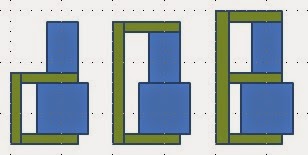
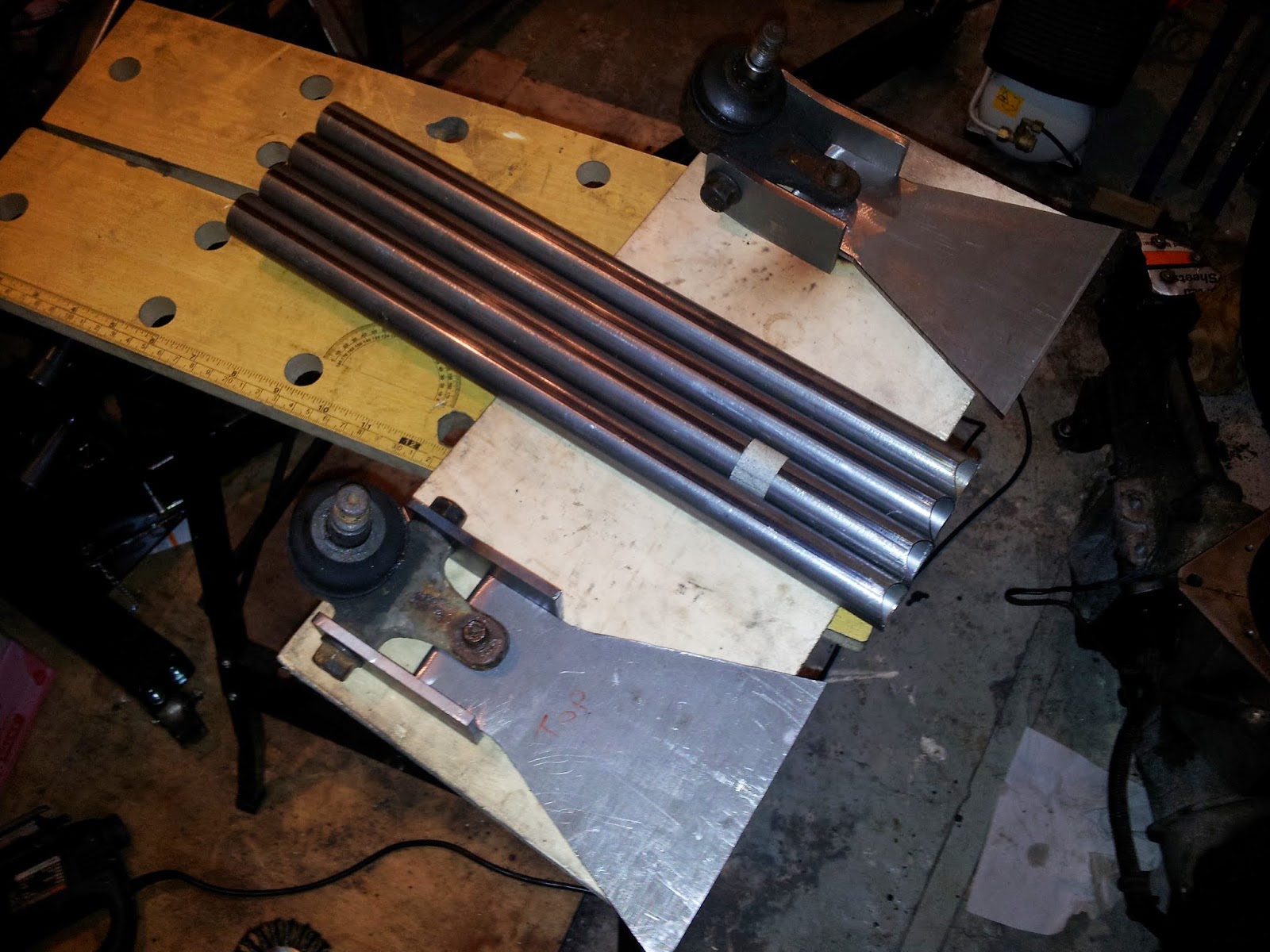
As the lower wishbones aren't handed, I did them all using this jig. That way I knew they would all be identically right (or identically wrong!). The plates I had cut for other parts of the suspension came in very useful as spacers, I kind of ignored the spacers suggested as it didn't leave all the seams in the centre. And when I was welding I wanted to make sure I was welding on welds.

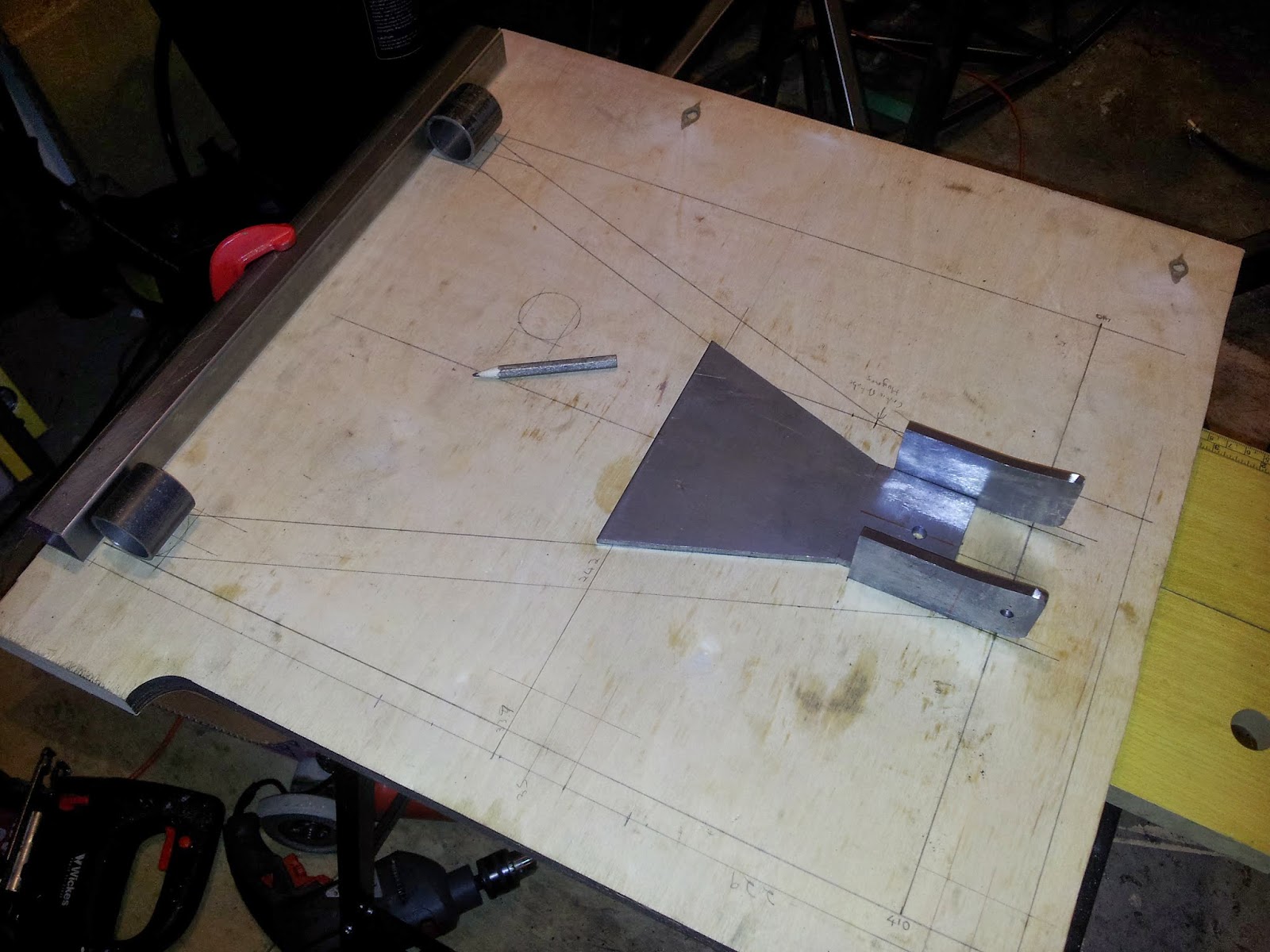
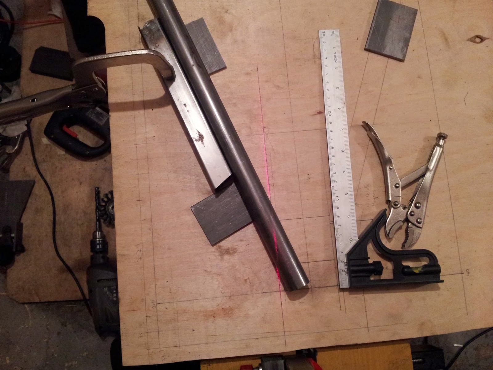
Then came the bottom cut. First I tried marking it with a laser beam;


But I couldn't get it to line up perfectly, so I went for an old fashioned handsaw jig. Again, lots of hours and lots of cutting fluid later, I had all pipes cut, and a full set of parts;


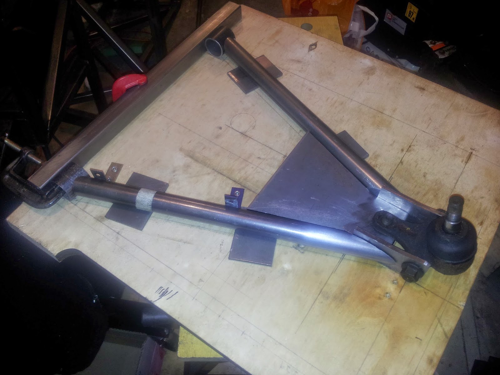
A first fit showed a bit of trimming needed;


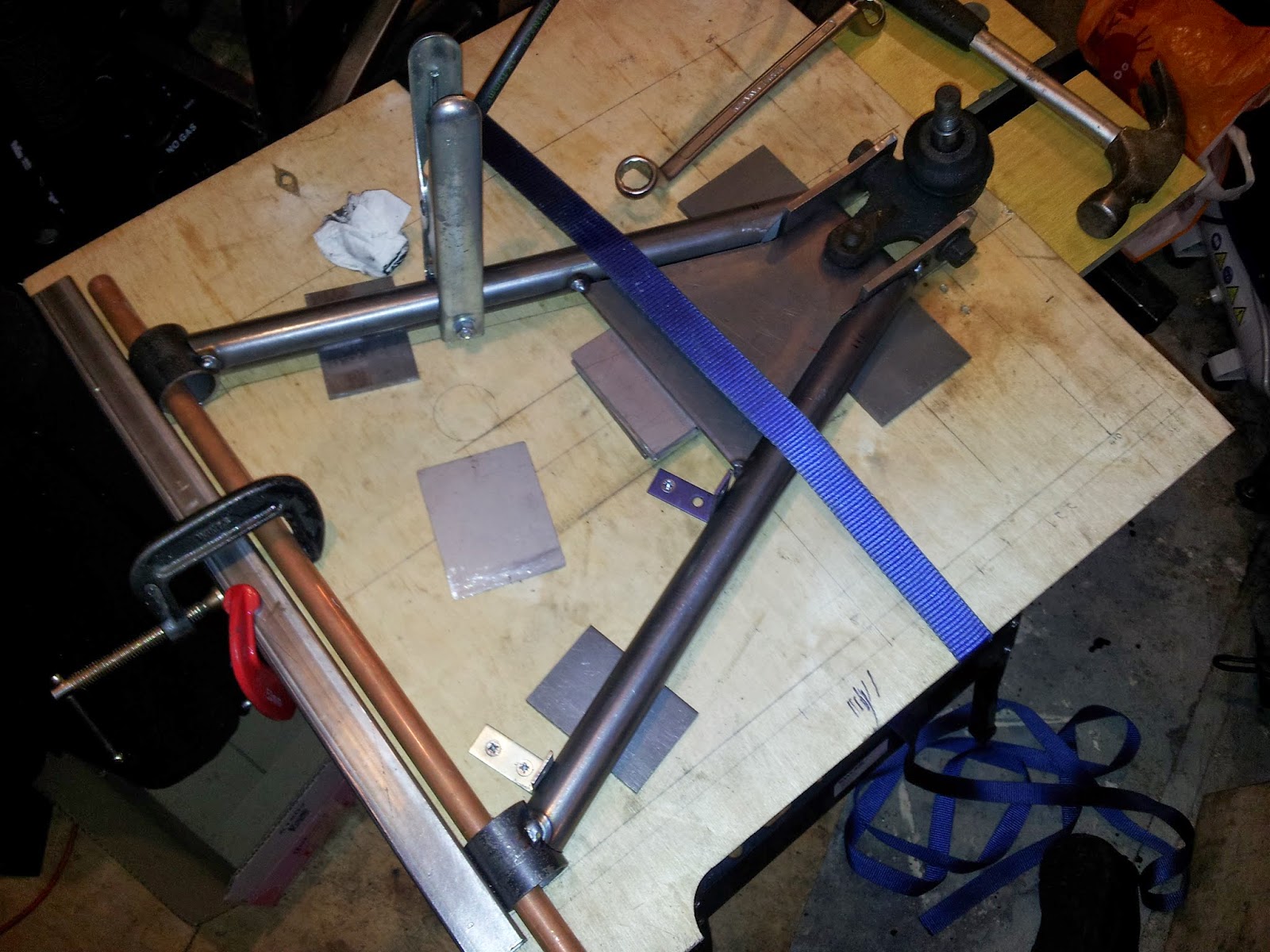
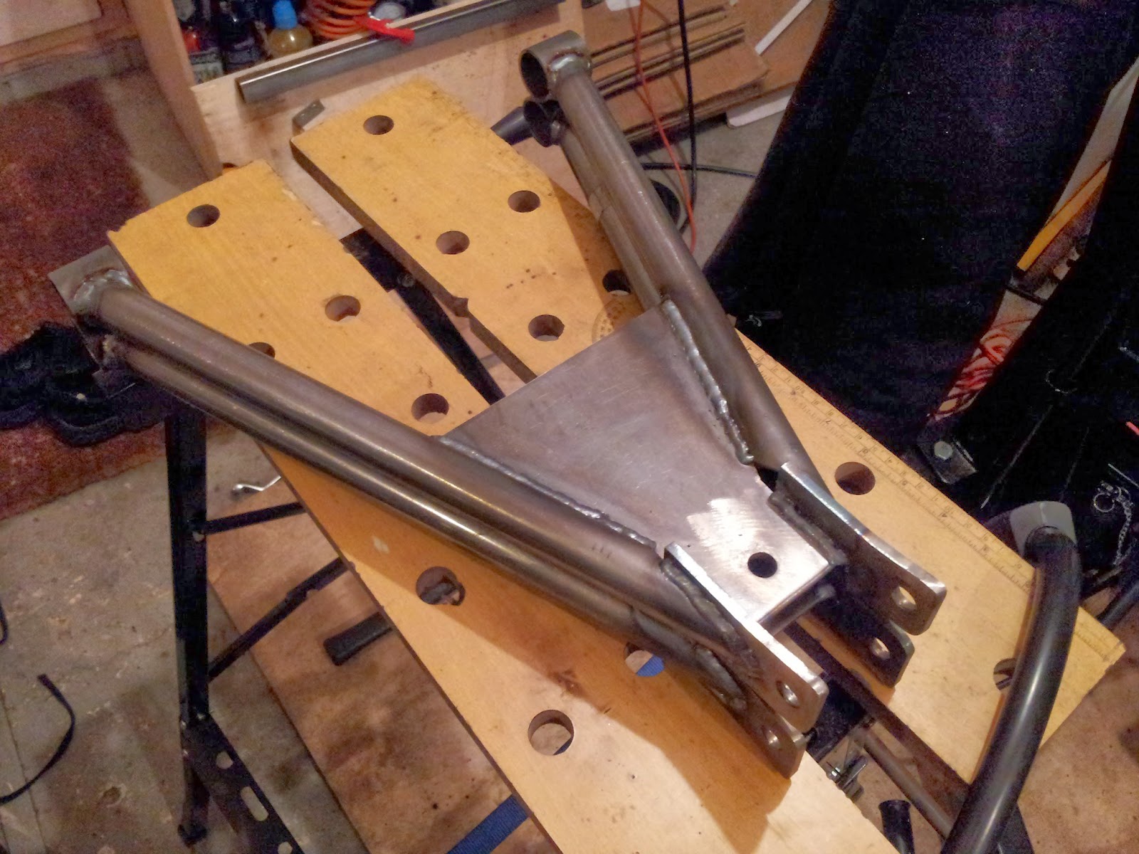
So ten minutes with a flap wheel on a grinder got them fitting perfectly. Straps and clamps aplenty ready for welding;


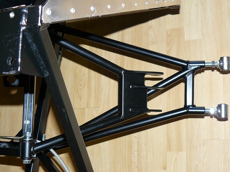
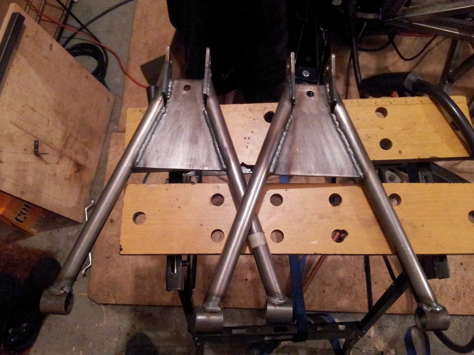
And a short time later I had two wishbones!


Putting them back to back showed that there was less than 1 millimetre difference between the bush tubes and the balljoint fixings, so I'm really happy. 


I just have a couple of holes in the end of the tube to finish off, but I might pour some waxoyl in there first. It'll probably all get burnt away as I finish the weld, but at least things will stay rust proof.

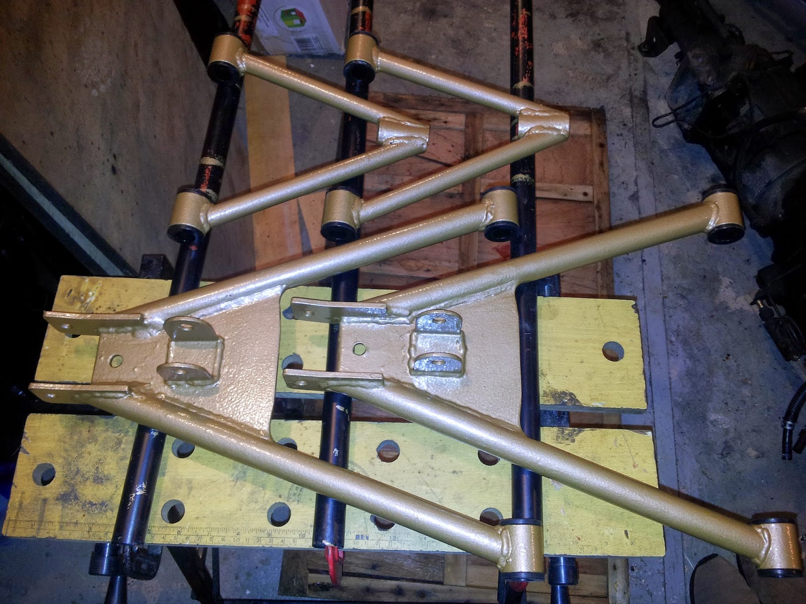
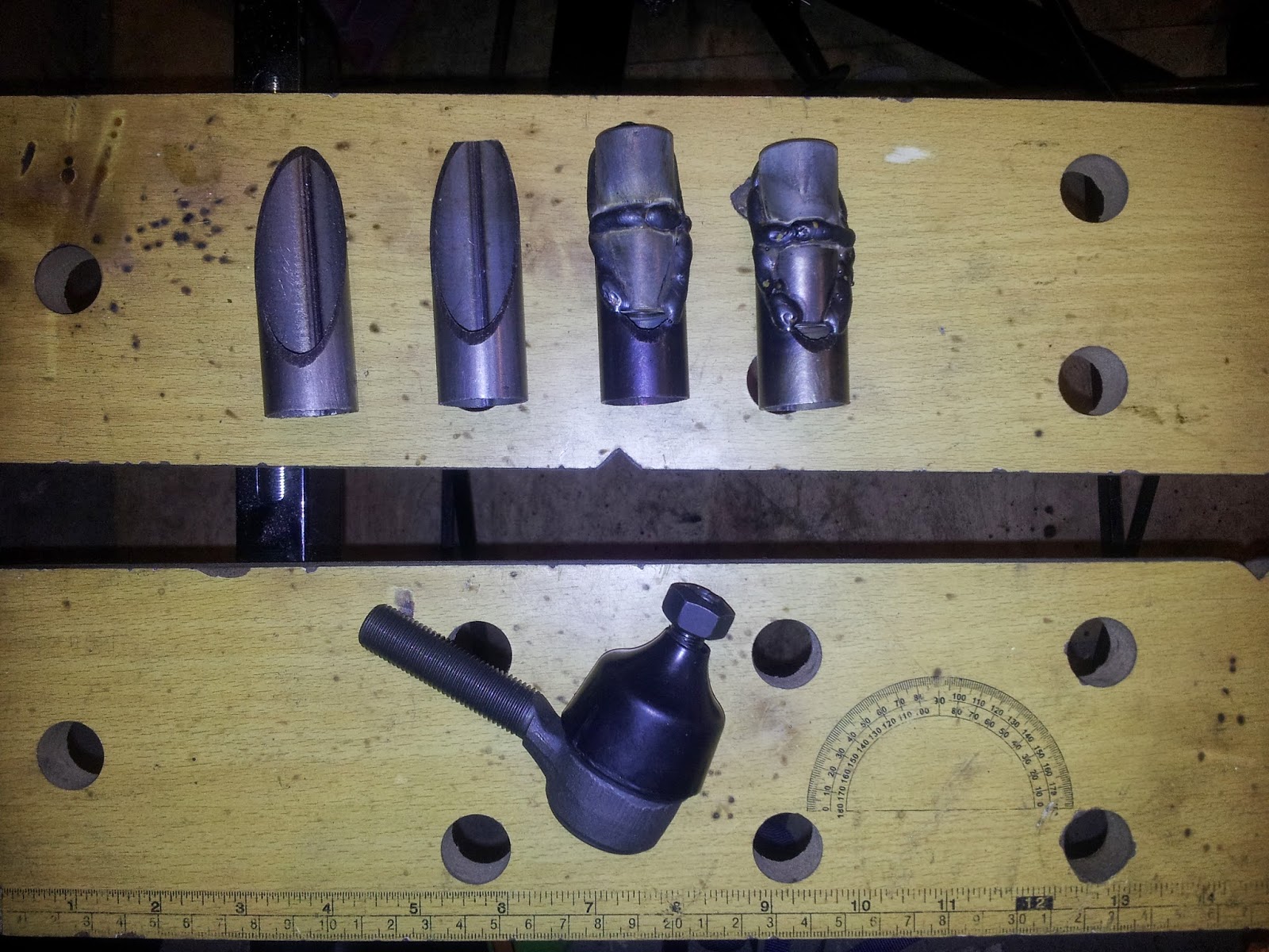
The cut tubes left an interesting profile, which got me thinking about the next stage. I need to sleeve the threaded inserts for the top wishbones, and I was advised to cut the sleeve at an angle to maximise the weld length. As it so happens, the sleeve tube is the same tube I used here!! So;


The two on the left are bare offcuts, the two on the right are the inserts welded into place. With them fully welded as they are, the BMW balljoint still fits perfectly. Tomorrow I'll grind down those welds, and put the other two offcuts on top. Once they're welded on, I'll have a completely sleeved insert with good welds holding it tight. It's still only 50mm long (the original plans call for 60mm) but the threaded part of the balljoint is only 50mm long so I'm not worried.

Monday 24 March 2014

Front suspension build

The front suspension is now coming together. I'm taking the MX5 measurements from the Saturn plans, but I don't want the lower adjustments. So I've kept the ball joint where it is, kept the bushes where they are, but brought the wishbone tubes out to between the two. So far so good, although cutting and shaping the fish mouths (is that the correct term?) has been an absolute ballache!!

But before I continued, I want to check what sort of suspension measurements I was going to get. So for camber, I have worked out the following (assuming horizontal suspension at rest);

Upper suspension distance from end of studs to the end of the wishbone (where the balljoint screws in) = 192mm.
Upper wishbone length from end to end = 242mm.
Total upper length (end of wishbone tube to end of studs) = 434mm.

Lower suspension distance from end of studs to balljoint bolt = 130mm.
Lower wishbone length from end to end = 410mm.
Total lower length (end of wishbone tube to end of studs) = 540mm.

On the chassis, the brackets are mounted as follows;

Upper brackets are 335mm from centre.
Lower brackets are 247mm from centre.

By my reckoning, that gives me distance from chassis centre to end of studs at 769mm upper and 787mm lower, a difference of 18mm. A rough calculation suggests this is a 5 degree camber, so I'm going to have to get it down to 4mm for a 1 degree camber (ideal start). I don't expect this to be an issue with plenty of space available in the adjustment.

I'll work out caster tomorrow, aiming for +6 to +10 so fingers crossed for 28mm difference top and bottom!

Sunday 23 February 2014

Post Christmas update

Yes I know it's February, and yes I know my last post was September, but that pretty much sums up the build to be honest. It's been dormant for about four months for various reasons.

Anyway, lots of updates;

Phil at Talon finally got me a new diff case, and it fits perfectly. He's also suggested a few things for fitting, mainly so I don't actually damage the casing while it's being fitted. I've also figured out that the two plates that I had for a Sierra diff can be chopped up and will become the fixings for this diff!

The casing arriving does mean I was able to crack on with the rear suspension frame, and that's all welded up. Well, on that subject the whole chassis has now been fully welded, and I'm really happy with the results (even if it took more than twelve months!). I am a bit short of metal now though, I don't have enough for the extra triangulation. At some point I'll pick up one more 1" section and a 3/4" section.

I also popped over to theflockkeeper (Ebay person) in Telford for some steel offcuts, and came away with a good selection of 1mm for panels, 3mm for brackets and 5mm for suspension parts, all for the princely sum of £60. I still haven't got a floor but I've got pretty much everything else. Now I have no excuse for putting together the wishbones!! I won't be panelling in the engine bay, I'm working on the assumption that it will have a full bodyshell over it so the panels are redundant. It might help with cooling as well.

I managed to run out of welding gas while doing the chassis, a quick journey to my nearest Hobbygas supplier got me a full tank for £30 + VAT. I'm really liking not having to pay rental on the cylinder! I've got through at least three rolls of welding wire as well, I would go bigger but I've heard problems with the bigger rolls and it's not a huge difference in price.

Another bargain found as well, a fellow LCB member sold me a full set of coilovers for £100. Platform and damping adjustable, they just need a bit of a clean up. They even had the spring rates written on the springs! They were off a locost chassis rather than a Haynes chassis, but I think the lengths are ok. The front look fine with good spring rates, the rears might need stronger springs and perhaps a modification to the mounts for the length.

So the next stage is wishbones and mounts... See you next year (probably!)...

Oh, and one last thing. I'm using a 1.6 MX5 as a donor, and as any MX5 owner knows, there was a design flaw with the crankshaft (google short nose crank for more details). So I decided to check before I got too much further with the build. Turns out I have the updated crank with the better fixing, so no self-detonating engine for me!! Yay!