Sunday 25 October 2020

Results from the weekend part 2: The handbrake

 Putting everything together for the brake flexi hoses made me remember something I'd decided on a while back. To get the rear suspension behaving itself I worked out that the uprights should be 'backwards'. IE the left will be on the right and vice versa. 

This had the positive outcome that the suspension bracket could be correctly fitted, but had the negative outcome that the calipers were on the rear. When I was doing the suspension I thought it would be a minor inconvenience compared to the much bigger problem of redesigning the suspension.

The 'minor inconvenience' might be a bit more of an issue though. I also have the added complexity of wanting a dash mounted handbrake (see the post from last week). This means that custom cables were guaranteed but I'm really not sure whether this sort of safety device is easily DIYable. A quick post on Locostbuilders suggests it's not that much of an issue for two reasons. One was that many people have redone the Sierra handbrake in order to get it to fit. The other is that I can use more of the standard handbrake than I thought I could.

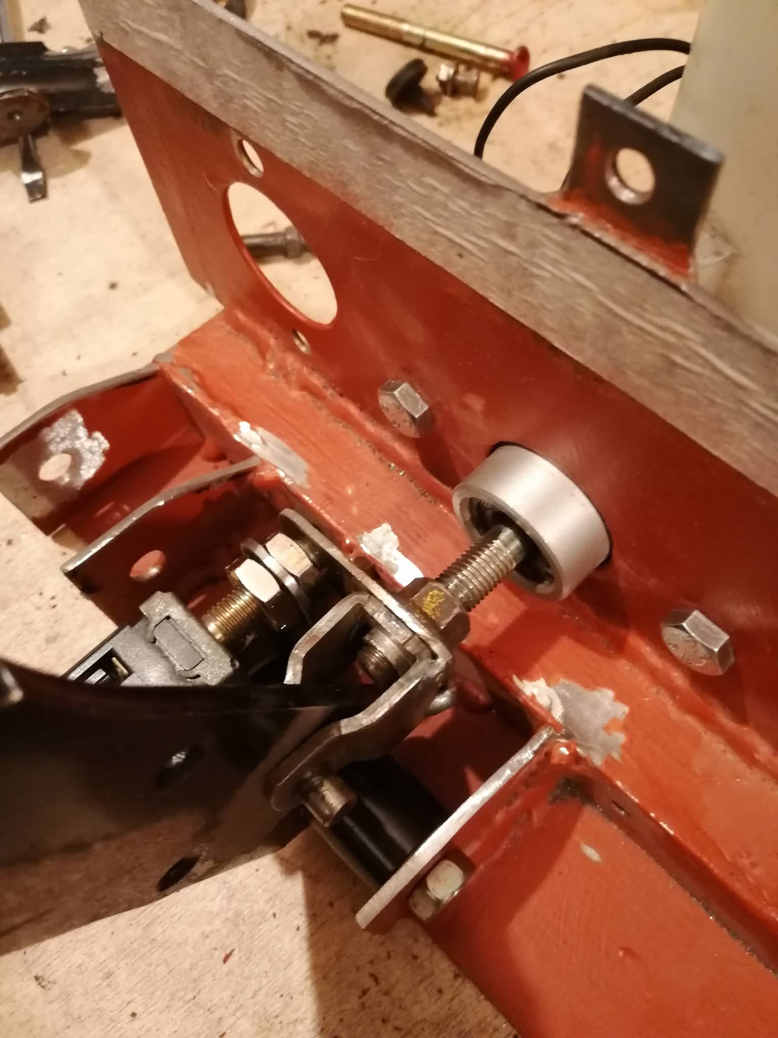
So this weekend I've spent a couple of hours freeing up the adjusting mechanisms on the cables. They took ALOT of work considering it's basically two nuts on a threaded tube!

The next job will be to put the suspension together (again!) and try and route the cable safely. The cable has got to come out the caliper towards the back of the car, then do a u turn on to the chassis (probably close to the brake pipes if I can get it to work). They then need to head up the centre of the car to reach the balance bar (oh yeah, I need to find out where that ended up!!), then onwards to whatever mechanism I'm using for the handbrake itself. 

I'm going to try and keep the rear cables as standard as possible, but the front one I think will have to be modified. After all, it's not even going to a handbrake! 

I'll get the rear rebuilt and take some photos so I can work it out... but that's it for this weekend. 

Results from the weekend

I managed to get some jobs done over the weekend, although the extra hour in bed did help. It does mean that there are no more light evenings, and it just gets colder from now on.

Still, jobs done. The first thing was to tidy up the hubs and uprights. They took a bit of a beating when I took them apart, in parts the metal was exposed. So back with the hammerite and black primer. It wasn't a major job, but it had to be done before things could go back together. 

The next job with those uprights was to work out the lengths of the brake flexi hoses. I had to basically build the suspension front and back on one side. That was an interesting experience, I'd forgotten how they'd gone together!! Still, after a few trials I got everything lined up and ready to measure. I had to get my shiny calipers out of storage too, the first time they'd felt fresh air since I reconditioned them and bagged them up.

I used the remnants of an extension lead to figure out the length. The wire was fed through the chassis brackets with the plug holding the end. The wire could then be routed to the caliper, keeping things smooth and not too tight. The fronts weren't too bad, just needed a bit of slack to cope with the steering and suspension movements. The rears needed a bit more thinking though.

The main issue is that the chassis brackets as suggested feed the flexi hoses straight out the side of the car. It's then a bit of a mission to get them back to the caliper without getting close to the wheel itself. This was especially relevant because my rear suspension setup had the caliper on the back of the disc rather than the front. This means both the hose and the handbrake would be heading towards the back of the car initially. 

After a few minutes trying to find a solution I decided to abandon the standard position. The plan is to have the flexi hose feed down from the caliper to the lower arm. Then pinned to the lower arm until it gets to the chassis. The chassis bracket will then be mounted at a suitable place, along the diff cage metalwork. 

I'll have to cut off the brackets and reposition them, not a biggie. At least it meant I could get the flexis ordered though, which is the first battle. I got them from Furore, they do custom flexis in a range of ends and colours for £20-£30 a corner (depending on length). I'm staying with the standard MX5 fittings, so it's a 10mm banjo on the caliper, going to an M10x1.0 female at the bracket. They come with a circlip and the copper washers so they should just bolt straight on. £102 for a full set, I was probably a bit over-cautious on the length but as they say, better to be too long rather than too short. 

Oh yeah, the handbrake. Separate post methinks...

Sunday 11 October 2020

Handbrake

 One of the things I've had in mind all the way through is the idea of an underdash handbrake. The demo HSR car had a handbrake right under the steering wheel, and while I was unsure about it being in direct range of my knees I couldn't argue with the clean look of the centre tunnel. 

The main issue is that it was still a handbrake, IE it was still the same handle and mechanism that would have been in the tunnel. This made it look odd (as well as the aforementioned knee impact). Other cars have had similar mounted handbrakes, and a quick google suggests there are much better options.

The easiest one to replicate would be the one used in some cars in the 90's. It was basically a pull rod inside a tube, attached to a cable and then on to the mechanism. 

There's a couple of things to consider though, the ratchet mechanism and the mechanical effort required to apply the brakes. 

The ratchet mechanism was achieved by having slots cut into the pull rod on one side only. To release the ratchet the handle would be twisted so the pawl no longer engaged. 

The mechanical effort needed some maths, based on the existing handbrake. The following measurements were made;

1. Distance from pivot to cable channel = 34mm.

2. Distance from pivot to handle centre = 240mm.

3. 19 clicks on the ratchet mechanism for full travel.

4. 45 degrees of travel for the handle.

The distances from the pivot means that the mechanical advantage is 240/34 or 7:1. IE the handle moves 7 times further than the cable. 

The cable travel is Pi x 68 / 8, or 26mm from stop to stop (the actual travel is less than that but I'll maintain the full travel distance for now). The same travel for the handle is Pi * 480 / 8, or 189mm. 

This means that I need to come up with a mechanism that moves 189mm on the lever, to 26mm on the cable. It shouldn't be too difficult, except that it's 'the wrong way'. The pull handle will come out towards the driver (front to back) whereas the cable needs to pull from back to front. A bowden cable would achieve this quite simply, but that would reverse the action without applying mechanical advantage. It would also add friction which would mean more effort and/or pulling distance. More than 7 inches is already a far pull distance, I wouldn't want it much longer.

I need to come up with a solution to apply the reverse in direction as well as operate the change in ratio. Time for some Fusion 360 I think!

Oh, for the ratchet mechanism, I counted 19 clicks on the ratchet. To have the same on the pull handle would mean 19 notches on the 189mm of pull, or 1 every 10mm. Not a problem. I need to have a spring loaded pawl to operate on the solid rod of the pull handle within the hollow tube of the slide. This is a little more of a problem but still not insurmountable. After all, I already have a handbrake with a pawl mechanism that I won't need anymore!


Bearings

 One of the things that has bugged me with the donor parts has been the wheel bearings front and rear. They didn't feel bad and were never highlighted as an MOT issue on the donor car history, but it seemed really strange to not replace them. The reason I'd not done them yet was simply because I couldn't get them apart!

Reading many forums seemed to agree with my assessment, they're usually so meshed together that they should only be taken apart if absolutely required. And it's very likely that some breakages and replacement parts will be needed. There was also mention of 20 ton presses, scaffolding poles as breaker bars, and all sorts of other stuff.

But doing some further research I could see that replacement parts weren't particularly expensive. On the front the bearing and hub were a single unit, as they are on the rear of most cars. Coincidentally they are actually used on the Mazda Demio/121 of a similar era (1990-2005). So while searching for MX5 front bearings gave a lot of very expensive options, a search for Demio rear bearings got lots of cheaper ones! A pair of hubs/bearings were £46 delivered.

Next were the rears. The stub axles were not going to survive, I resigned myself to that. The nuts were also going to end up in fragments on the garage floor. Fortunately the stub axles contain the CV joint so they're intended to be a replaceable item. These are MX5 items only, but a pair cost £31. They also come with replacement nuts so that meant I could go to town on those without worrying.

The last item for the rears was the bearing itself. Apart from wanting to replace the bearing anyway (the whole point of this exercise) the design of the stub axle means that the bearing collapses when it's being removed. So it has to be replaced. Again, Mazda makde things really simple and had this wheel bearing used by many cars. £25 for a pair, no problem.

This meant a full set of replacement bearings and associated parts was £102 delivered to the doorstep. That's pretty much spot on in my opinion. 

The stripdown was so much more effort though. The four hub nuts got the brunt of the angle grinder and powerfile, and did indeed end up as bits on the garage floor! 

I have a decent hub puller from previous car maintenance, so with a bit of encouragement the fronts came apart quite easily. The new ones will go on, and then torqued up as required.

The rear took much more work to do the same task. In the end I got my impact gun on to the hub puller and just gave it everything I had. The vibrations of the impact gun, combined with the immense pressure that a hub puller can apply, managed to press the stub axle out of the hub. After removing the bearing internals that had just collapsed as expected, the outer race was then hammered out of the hub. Finally the last job was to detach the stub axle from the driveshaft, it was just a spring clip holding it in the same as any other driveshaft so a few thumps with the hammer sorted it.

Once all the parts were cleaned up (CV joint grease is really horrible stuff!!) the parts can go back together again. At time of typing this update the bearings have been pressed into the uprights, and I've done some cleanup on the hubs ready to give them a lick of paint. They had been painted before but access issues meant it was a bit of a rubbish job. 

So that's it for the bearings, everything is where it should be and it'll be ready to bolt back together in the final position. Another job ticked off the list. Well, it was a job added and then ticked off, but it needed to be done! 

No pictures on this one, with the various bits of metal going all over the place and lots of hammering I thought my phone wouldn't last very long. In fact I was fairly accurate with my estimate, I had since found a bottle of beer with a severely dented cap, and I had a pencil torch that ended up in pieces and has been glued back together. 

Pedal setup completion

 Well, it's Sunday morning, the coffee is nice and for once the sun is out, so it's time to get up to date. I've done a fair bit of work over the last few days, actually a bit more than I expected to be able to. 

The first thing to update is the pedals. As I had put in the last update, I had a brake and clutch switch to add. The brake switch was an obvious one, I need brake lights. The clutch switch was an odd one though. Apparently it's to cut fuel on overrun, and it's not difficult to just delete it. So I have!! 

That leaves the brake switch. The action of the switch is to have it closed when the pedal is not pressed, and open when the pedal is pressed. When the pedal is in the MX5 this means it's mounted above the pedal, out of the way of the drivers foot. That doesn't work here as I've turned them over. So I needed to mount it on the floor. This is how I've done it;


It's out the way of the foot, and works as required. It also has the added benefit in that the screw fit of the switch is now the end stop for the pedal. Combined with the screw fitting of the push rod and I have full control over the pedal travel. Obviously where it is at the moment is very wrong, but once the system is plumbed in and pressurised I should be able to figure out a nice place for the pedal to sit. It 'should' only need maybe a couple of inches of travel to apply full force, so it'll be adjusted to do that.

Here's a better view of the same;


Next is the clutch pedal. No switch means no end stop, but the solution was much easier here. The book uses a bent piece of metal mounted on to the bolt itself. So here's the same for mine;


The adjustment is simply to rotate the metal until it's in the right place, then tighten everything up. The screw thread on the push rod also deals with travel. This also needs plumbing in and adjusting, I don't know how much travel is required here but clutches tend to move a lot further than brakes.

Finally the gas pedal was mounted to the chassis. This wasn't a complex one, just a U bracket on to the rail itself. It's spring loaded to assist with pulling the cable, and there's a screw fitted into the bulkhead to restrict travel. I must take a photo of the whole set up, but in the meantime here's a better photo of the final clutch/brake setup;


I am really happy with how it's come out, I'd done the back plate quite a while ago but not finished the process until now. It's had a coat of paint on all the parts and is ready to fit to the car.