Tuesday 24 September 2019
Gearbox bush
Just a quick one for now, the gearbox bush. After trying to figure out what words to google in order to find something suitable, I finally managed to find 'Landrover V8 engine mount'. A bog standard round bush with two threads either side for fixing. It'll be working under compression, and I just need a bit of angle iron to fix the mount to the car and the gearbox. Nice and easy... :)
Sunday 22 September 2019
Clearance around the engine
The other side of getting the engine in is to see how much clearance around the engine is available. This is quite critical as I don't want to be fitting pipes and other stuff where the engine goes. Fortunately, it looks like there's plenty of clearance all round;


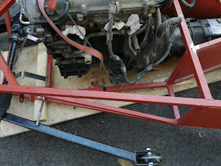


In fact, the only slight issue will be the clutch master cylinder. It's a bit tight. But then again, so is the Saturn picture example, with the pipe from master to slave being about three inches long! With a bit of lateral thinking I could convert it to a manual clutch very easily... I won't, but I could.
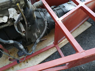
The other main tight point is where the gear shift is;
But even that isn't that tight. The pipes and electrics have to come below the cross bar anyway, then the fixings are vertical so I can put them in any combination and they'll work fine.
I do need to figure out that reverse switch, every picture I look at with it in shows that it's awfully tight.
Well, that is it for this weekend. My back, arms and legs are absolutely worn out so this write up is the only 'car' time I'll be doing today.


In fact, the only slight issue will be the clutch master cylinder. It's a bit tight. But then again, so is the Saturn picture example, with the pipe from master to slave being about three inches long! With a bit of lateral thinking I could convert it to a manual clutch very easily... I won't, but I could.
The other main tight point is where the gear shift is;


But even that isn't that tight. The pipes and electrics have to come below the cross bar anyway, then the fixings are vertical so I can put them in any combination and they'll work fine.
I do need to figure out that reverse switch, every picture I look at with it in shows that it's awfully tight.
Well, that is it for this weekend. My back, arms and legs are absolutely worn out so this write up is the only 'car' time I'll be doing today.
Engine mounts
The main reason for getting the engine in is to sort out the engine mounting. I couldn't find much information for reusing the standard mounts, with most using a solid mounting or at the very least the standard landrover rubber mounts.
Of course, I didn't want to do that. The standard mounts look really well engineered, and with a metal case around them that is bolted to the chassis I did think they could be reused very easily.
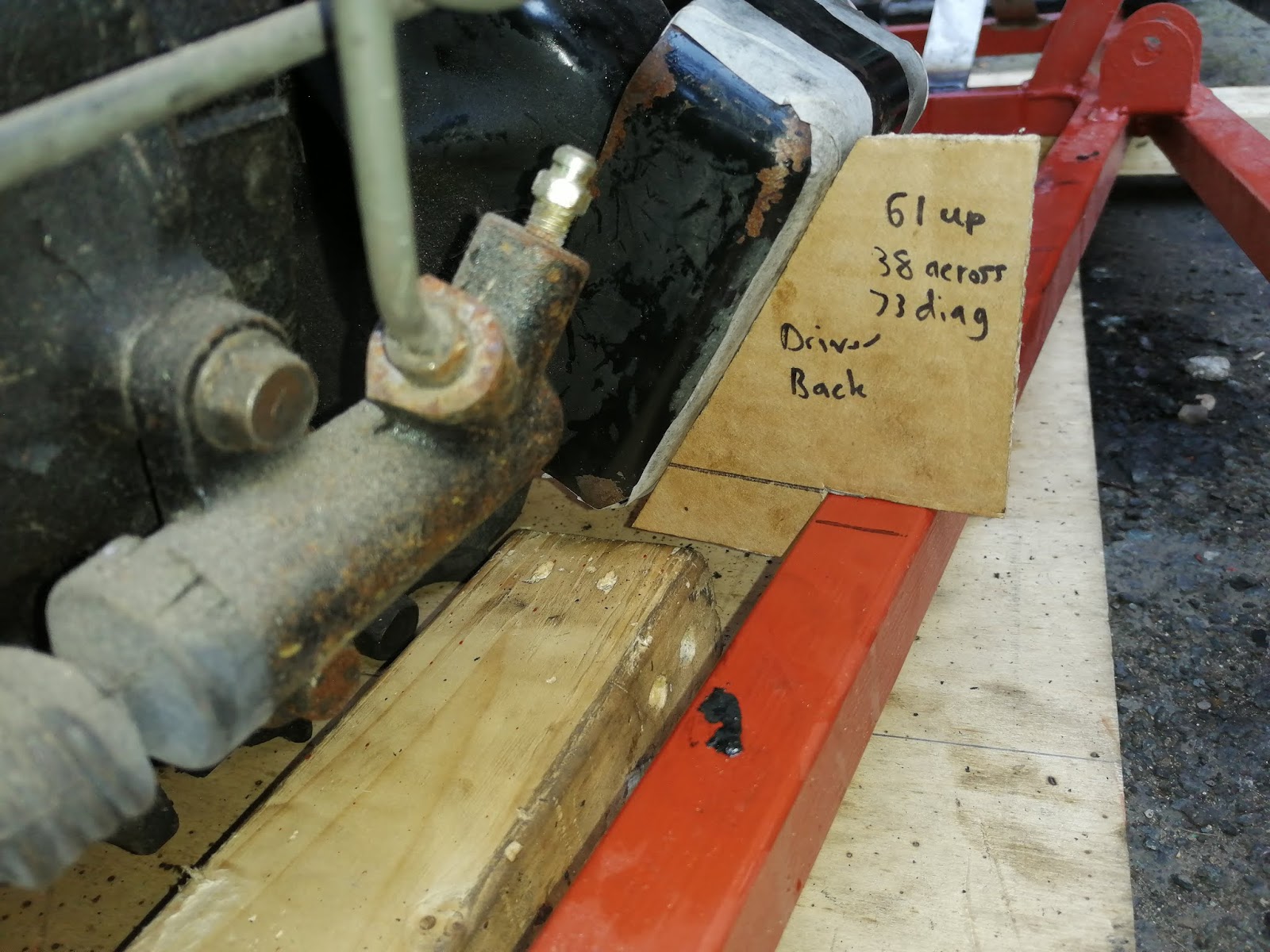
Once the engine was in place and the sump was 1 inch below the frame, I had this on the passenger side;


This is for the drivers side, there seemed to be a slight angle to the mount so I did a front and back one. But then the same task on the passenger side only needed one. They're also very slightly different angles. But I can check that again when they're off the car, as the part that bolts to the engine is meant to be vertical. I've also marked their destination on the frame.
The plan will be to reinforce the frame with some 1 inch RHS, then build up the existing box for it to bolt down to the frame. Similar to this;

But this doesn't reuse the box so I'll have to tweak it. I'm also confused why the middle of the bar appears to be missing as that appears to significantly weaken the frame so I won't be doing that!!
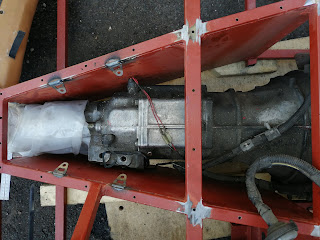
More on that later when I build them up. Now the gearbox mount. The one picture I saw reused the PPF bolts along with a metal plate on to a rubber mount;

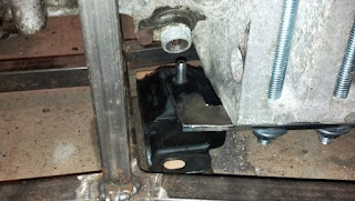
This seemed like a reasonable approach, but when I fitted the engine I found an alternative option that would work in a similar way but perhaps be easier to implement. This is the bracket that I'm talking about;

Of course, I didn't want to do that. The standard mounts look really well engineered, and with a metal case around them that is bolted to the chassis I did think they could be reused very easily.
Once the engine was in place and the sump was 1 inch below the frame, I had this on the passenger side;

And similar on the drivers side;

They were in a good position relative to the frame, so it seemed like I was on to a winner. Next job was to make some cardboard templates for the profile. I only need to get them in relation to the frame, so this is what I came up with;

The plan will be to reinforce the frame with some 1 inch RHS, then build up the existing box for it to bolt down to the frame. Similar to this;

But this doesn't reuse the box so I'll have to tweak it. I'm also confused why the middle of the bar appears to be missing as that appears to significantly weaken the frame so I won't be doing that!!
More on that later when I build them up. Now the gearbox mount. The one picture I saw reused the PPF bolts along with a metal plate on to a rubber mount;


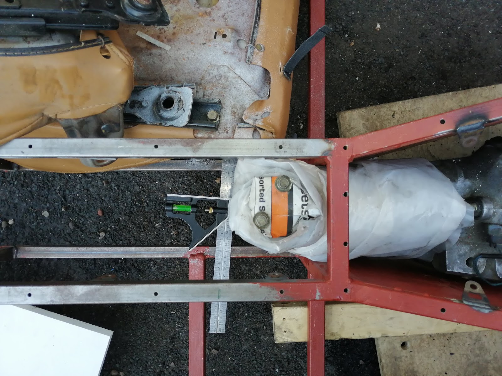
This seemed like a reasonable approach, but when I fitted the engine I found an alternative option that would work in a similar way but perhaps be easier to implement. This is the bracket that I'm talking about;

The gap from the bottom of the bracket to the frame is 23mm, with the centre of the bolt hole being 28mm from the front plate (and 20mm from the front of the bottom bar, which considering the two distances should add up to 44 doesn't quite make sense but it's close enough!). If I can make up a bracket to go from the frame, through a rubber bush, to the two bolts, I should be able to get everything in the right place and secure. It'll need to be bolted from below, as both sides will be filled in as soon as the aluminium panels get fitted. I'll double check all that as I may need to use a slotted hole to keep things easy to align. Oh, and the two holes are evenly spaced from each other across the centre line, so without that bracket I should be able to centre the engine a bit better.
So that's three more chunks of work that I can complete which is good.
Next job... engine!!
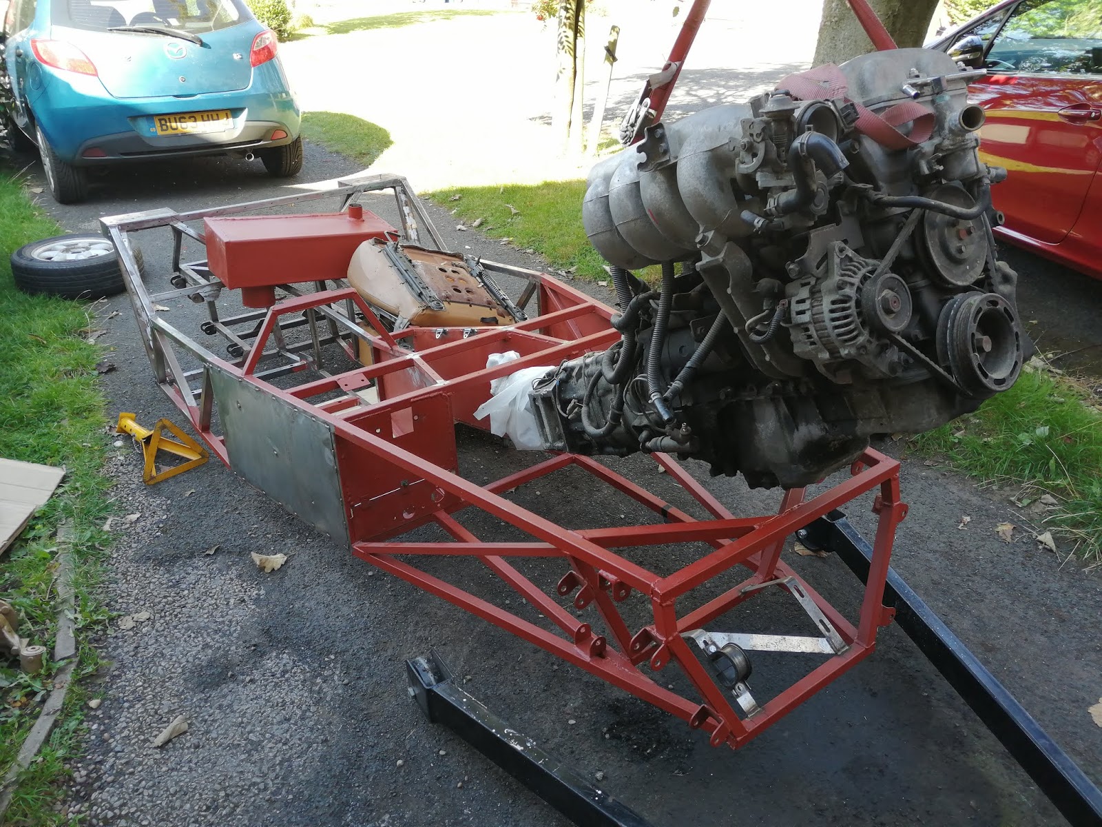
OK, I did say the next job was brakes, but the stars aligned for probably the last time in the year. A free Saturday, sunny weather forecast, so I finally got to get the engine in.
First thing then. I mentioned a while back that the documents talk about a cross member that needed to be removed, but I couldn't figure out why. Well, now I know!! It took about five minutes of moving to realise the engine was not going to get past that particular lump of metal. It didn't last long with the angle grinder, at least to a point where the engine did fit. I need to tidy the ends up and cap them off, but that's an easy task.
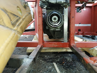
A few photos to start then. This is the engine mid-flight, with the offending bar still in place;
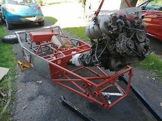
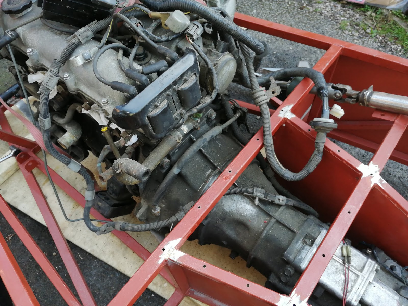
Once that was out the way the engine went into place quite easily;

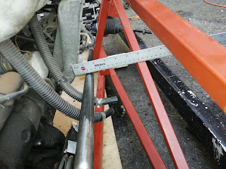
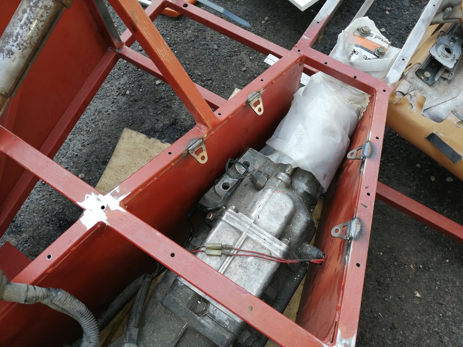
I'd say maybe half an inch gap on the drivers side, and zero gap on the passenger side. That reverse switch will need protecting or possibly the panel 'adjusting' to compensate. But the gear shift is in a nice place;


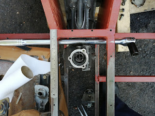
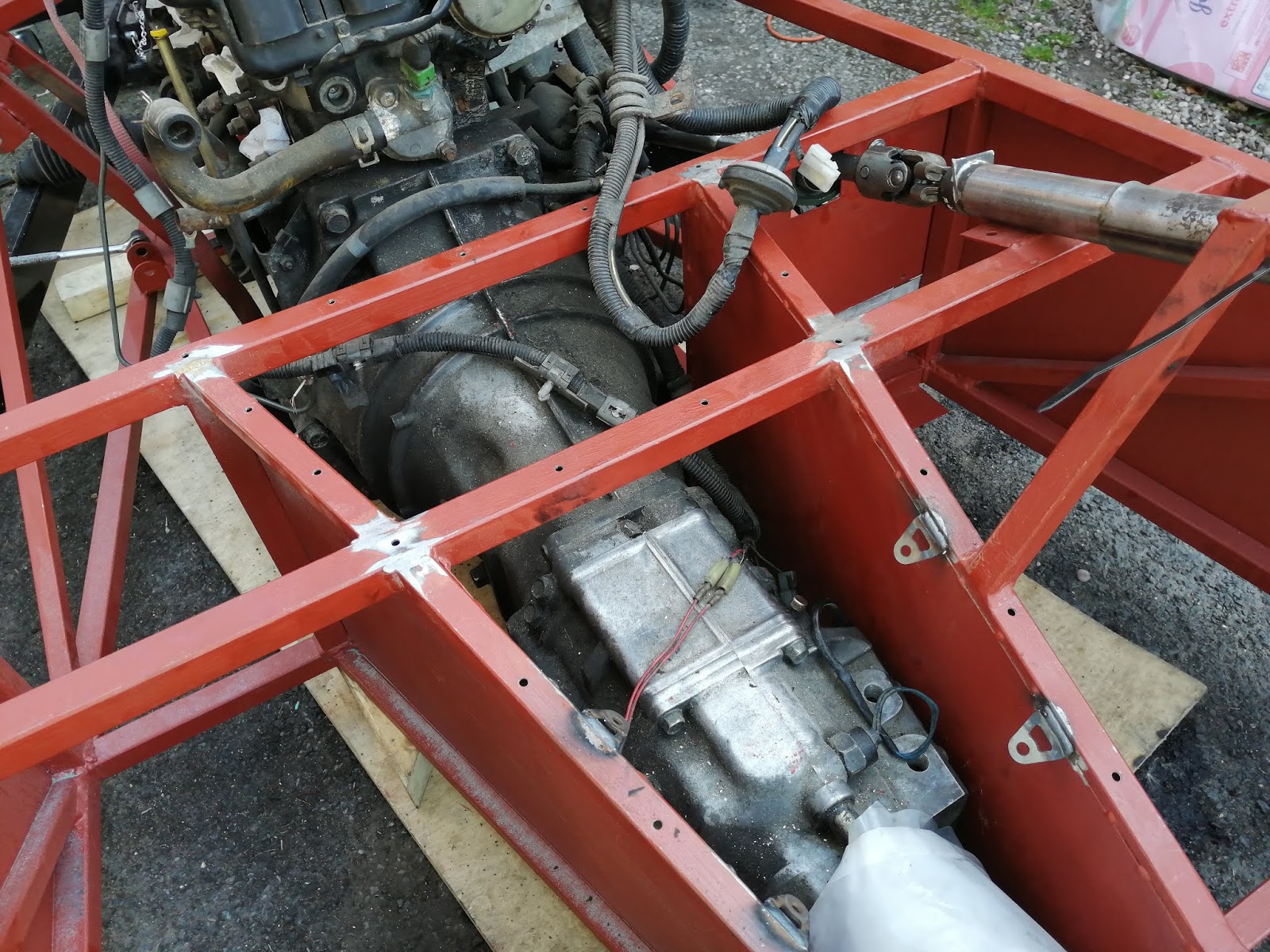
It does appear slightly off centre here but that's because of the lower bracket. And on the subject of the lower bracket;
This is the offending part, this is stopping the shift and the prop from being in the centre. But it's also a fantastic place for the front gearbox support. Once that plate has been removed, I have two chunky bolts going into pretapped holes, all just begging for a custom bracket leading to a rubber mount. This is similar to how the Saturn plans describe it, but theirs is a hard bracket and I'm not happy with that.
All in all a really good day. I'm not going to put much else into this post as I need to separate out the information. Time to get on to those then.
First thing then. I mentioned a while back that the documents talk about a cross member that needed to be removed, but I couldn't figure out why. Well, now I know!! It took about five minutes of moving to realise the engine was not going to get past that particular lump of metal. It didn't last long with the angle grinder, at least to a point where the engine did fit. I need to tidy the ends up and cap them off, but that's an easy task.
A few photos to start then. This is the engine mid-flight, with the offending bar still in place;
Once that was out the way the engine went into place quite easily;
Unfortunately I forgot to take a wide shot, but then again I was doing this for positioning rather than pictures.
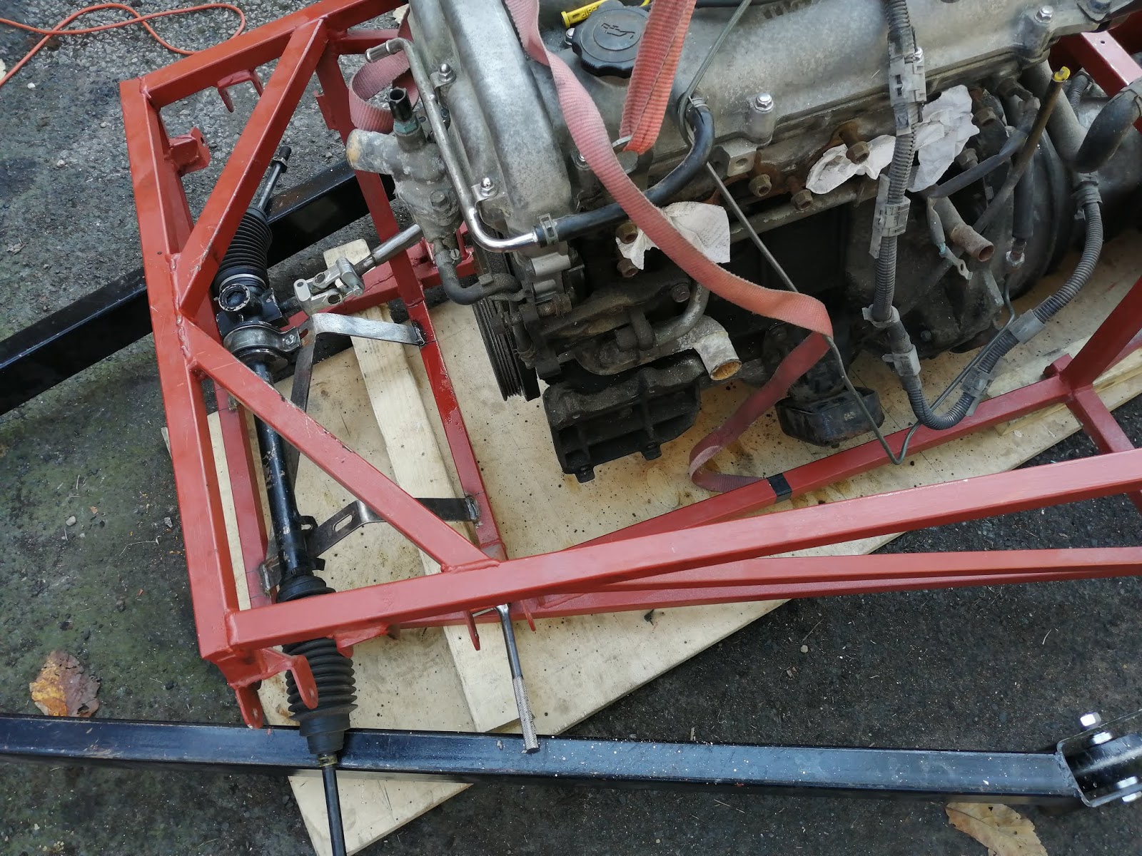
On that subject, there is a fair bit of space available. One comment was that the steering column needed a notch cut out of the inlet manifold support. Not for me though, I think it's because I had moved the steering column to give me the 10 degree angle;

Although I wasn't sure why the steering column was resting against the chassis vertical. It could be because it wasn't bolted tight, but even if it shifts when tightened up I still have a bit of space available.
The tightest area was the transmission tunnel. With the engine mounted as far back as possible, I had this left;

It does appear slightly off centre here but that's because of the lower bracket. And on the subject of the lower bracket;
This is the offending part, this is stopping the shift and the prop from being in the centre. But it's also a fantastic place for the front gearbox support. Once that plate has been removed, I have two chunky bolts going into pretapped holes, all just begging for a custom bracket leading to a rubber mount. This is similar to how the Saturn plans describe it, but theirs is a hard bracket and I'm not happy with that.
All in all a really good day. I'm not going to put much else into this post as I need to separate out the information. Time to get on to those then.
Sunday 15 September 2019
Next job... brakes
Time to crack on with the brakes. It's reusing the split system in the original MX5. This is a three outlet design, with the two fronts on individual lines, and the rear on the third. The rear also includes the brake light switch before heading off to a T junction mounted behind the diff. Once there, each side gets an individual feed.
The fronts come out of the master cylinder on to the two lower rails just in front. From there they run along the rails until they get to uprights U1 and U2. Then it's to a bracket that is welded to the top of the upright, and a flexi finishes the route to the caliper.
Rears are similar, although with the brackets I've installed they pipes will actually come up to the top of the tunnel first, then routed back to the T piece which will mount on the back of SB3. Then it's off to either side, again staying above the suspension to arrive at a bracket, then a flexi off to the caliper.
So first job will be to find the master cylinder (wherever I put it!!), fit that and the T piece in place, then weld the remaining brackets in place. Or thinking about it, I'll need to weld a bracket in place for the T piece!
Time to get started and see how far I can get in a day.
Jobs list
I don't like doing these as it makes me realise how much work is still to go, but it's got to be done.
In no particular order;
In no particular order;
- Fuel tank mounting bracket. Normally there is a full frame behind the car for the rear panel, in my case the rear panel is all fibreglass. Without the full frame I still need something for the fuel tank, so I'll take part of the frame where it supports the tank. Problem is, this makes the car longer than my garage... I'll have a think what to do here.
- Whilst I remember, the fuel lines will need to be routed. But that will go along with the brake brackets and wiring loom within the transmission tunnel. And I need to buy the fuel line too. And connectors.
- Handbrake mounting. This is going underneath the steering wheel, which does reduce leg room but it also keeps it off the centre tunnel which is what I want. The equivalent plates are CP12 and 13 (P47) so I'll adapt those to fit.
- Brake lines. This is another big block of work consisting of;
- Brake line supports on each corner (P51).
- Finish welding on the tabs all along the inside of the tunnel.
- 3D print pipe brackets (or go for P clips).
- Hard brake pipe fitting.
- Handbrake cables. I need to check what's needed here, particularly as I'm moving the handbrake. From memory there are two cables from each caliper, that come together in a 'balance bar' arrangement that goes to the handbrake.
- Engine mounts. This needs the engine fitting for position, which in turn needs a full day and some dry weather. Fingers crossed for a warm winter here...
- Pedal box tidying. This is mostly built, but it needs a couple more fixings and needs a bit of loosening up. From memory it only just fits, even the application of paint stops it going on easy. I'll need to get this working better if I have any hope of fitting it with everything else in place.
- Check the steering rack for fit. I have brackets for the rack, I just need to find out if they go on ok.
- Fuel tank straps. No issues here, just a couple of 1mm steel straps that are folded as required. I'll need the mounting bracket done first though.
- Scuttle panel. This needs the bodywork fitting to see what gap is to be filled.
- Electrics. Erm... yeah. Lots of. Spaghetti. The wiring loom is still in a carrier bag and needs to be laid out and routed. It's not complicated, but it will be fiddly and time consuming. Oh, and I think I'll need to buy some lights! I have some from the donor, but not a full set.
- Seat modifications. As mentioned earlier, the seats don't currently fit so I need to modify the seats.
- Body fit. Big job here, as with the engine fit it'll be an outside job that could take a day or so. Trial fit the bodywork, make brackets as required, fit the bodywork, rinse and repeat as required.
Oh... that isn't as much stuff as I had expected!!
Interior finished...


Well, that's a huge chunk of work now done. I've spent god knows how many days just on these panels, mainly because this is the primary 'visible' part of the car. Pretty much everything else is going to be covered by the bodywork, this is what I'll see every time I get in the car.
I didn't really have too many issues with it, I think the main thing I have worries about is the tight fit. I got all the panels down to the closest tolerance I could get, I reckon maybe a tenth of a millimetre in some cases. If there was swarf left on a drill hole, that was enough to misalign the panel!! The problem then comes from the adhesive I'm planning to use alongside the rivets. The adhesive will take up an amount of space, even if it's the tiniest amount it's still going to take up space. I suspect I will need a bit more 'refinement' when it comes to actually putting the panels in place.
So that's it, that's that job done. Now it's time to take all the panels off and store them somewhere, then figure out what the next job will be. I'd best go get the book and work through my list...
Sunday 1 September 2019
Back after the summer break
Well, now that all the fun and games of summer is done, I can finally get the car back on track. First thing, figure out where I was;

This is all the panels as they are at the moment. It looks like I ended the session with the two outer side panels yet to be cut to shape, and the two inner panels to be trimmed along the top. I'm guessing the trimming on the top was because of the centre panel not being done yet.
And just to see what it might look like, I couldn't resist fitting all the panels temporarily;

I just love this look, it really shows how things are going to come together. Even with the panels not quite adjusted together, I can see the interior and how it'll look. I'm very happy with how it's working, and can't wait to get everything finished here.
It has given me a few things to think about though;
1. The passenger footwell end. No biggie, just a bit of metal to fix in place. Probably welded in steel as that's what the drivers side is. For some reason I keep forgetting it though.
2. There's a slight gap where the back panels meet the floor panels. Again, no biggie, I was going to put sealant around the edge anyway. And it's hidden by the seats.
3. The seat bases don't fit. This is a bit more of a biggie. I knew that they were going to be tight, I didn't appreciate how tight. They basically just don't get anywhere near where they need to go. It looks like I'll have to remove the squab and do some quite severe modification to the base metal. It's quite lucky that I've had to replace the heater elements in my main car, as it's taught me some valuable lessons on how to remove leather and foam!!
So next step is to get the side panels finished off, do the centre panel as removable then trim the other side panels to match.
Subscribe to:
Posts (Atom)