Monday 5 November 2018

Fuel tank part 1

I'm currently welding up my fuel tank. Whilst it's a little slow going due to available time, it's not really bringing up any issues. At least that's what I thought. Turns out at the bottom of the page in the Haynes manual is mention of having to add a swirl pot to the tank. But no clue on how large to make it.

Cue a quick question on LCB. The general consensus is;


  • Deeper rather than taller. This is to stop the fuel sloshing around. Make sense.
  • Outlet near the bottom. Again, makes sense.
  • Return to the swirl pot. This is an interesting one, I was going to put it back near the top of the tank but into the swirl pot makes more sense.

And then it's just the size. Apparently enough to maintain cornerning fuelling is the guide. So, how long is a piece of string. Back to number crunching for this one.

Based on a fuel pump that can deal with 255 litres per hour (an uprated mx5 pump), I need to give it 4.25 litres every minute, or 70ml per second. Add in a 10 second corner, that means it needs at least 700ml constant supply. If I assume a 1 litre requirement (to give a bit of leeway), that should be enough. Well, it's probably overkill, maintaining a 10 second corner with enough G's to keep the fuel out of the swirl pot would be so far beyond my driving skill it would be silly!

However, having the inlet and outlet on the swirl pot means that the tank itself just needs two holes cut. One for the filler and float, one for the swirl pot. I'll make one side of the pot flat so I don't have to deal with fuel connectors on a curved surface.

I also plan to make the hole in the tank a bit smaller than the swirl pot, in order to make a small lip. That should also stop fuel splashing back out and into the tank.

And then I'll probably be really paranoid, always drive with at least half a tank, and never ever have to worry about fuel starvation!!

Sunday 30 September 2018

Catchup

...And just like that, two months have gone by. I often thought I'd have more time to do stuff as I got older, turns out there's just more stuff to do!! It's partly my own fault though, it shouldn't take much effort to get into the garage and work on the car.

Anyhow, here's where I am. The footwells are nearly finished, I've cut all the metal and just need to weld on the last three panels. A quick coat of paint for that and then I can move on.

I have three sheets of metal in the garage now. Two sheets of aluminium, one sheet of steel, all three are 2 metres by 1 metre. They came from The Metal Store, and while the final bill was £124, that was including delivery to the door which was proving to be the most challenging part of sourcing it locally. Because I needed it in pretty large sheets (as opposed to the steel bar which could be transported much easier), even if I could have bought it from the next door neighbour it would have still been challenging to get it home. 

Comparing it to current prices though, I don't think I paid too much over the odds. There are people who seem to get huge swathes of metals for pennies, but I seem to have to pay normal prices.

The two aluminium panels are going to be for the rest of the cabin (so two side panels, the floor panels and the transmission tunnel cover), with the steel mainly there for the fuel tank. I gave up trying to source a ready made one, there were some second hand ones but they were either tatty, overpriced or a fair distance away (and fuel tanks don't transport well). And on the subject of fuel tanks, that'll be my next job after I finish the welding for the footwells. 

The footwells have actually been done a little differently to the book (and a typical seven). For my car with the Healey body, it's actually more important to me that the interior is better than the exterior (at least on the frame). I also want to give my feet as much room as possible, as it's a bit tight in there. So I've decided to have the forward section done so the metalwork is on the outside of the footwell, then the rearward section is done so the metalwork is on the inside. This gives me a smooth interior surface, but an extra couple of inches at the bottom. 

This does create some interesting challenges though. The main one is how it fixes to the frame. The welded panels are easy, but the aluminium panels are to be rivetted where there is nothing to rivet to! This is mainly around the seat back panel, as under normal circumstances that panel would cover all of the frame. I'm thinking if I can make that panel slightly oversized then I can create 'tabs' round the outer edge. Whether this works in practice I have no idea, but I'll give it a go. 

Thursday 26 July 2018

Extended steering

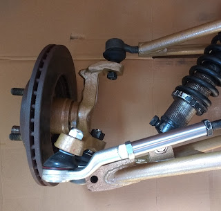
Well, the extenders have arrived, I reckon I spent all of five minutes before I had to try them on for size, and five minutes after fitting one I forgot I'd not taken a photo... here is the 'other' one;


As you can see, these are really well made. The male thread is for the MX5 TRE, and the hole in the right hand side is for the Sierra rack.

It did occur to me that the steering rack lock nut was designed for the Escort rack, and wouldn't fit on the MX5 TRE. I had to refer back to the picture I'd been sent to realise the extender fully screws into the TRE (and can be spannered tight), then the female end is where the adjustment is made.

This is what I had before, the Sierra extender in place but no room (and wrong thread) for the MX5 TRE;


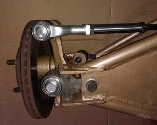
I wasn't going anywhere with that one. Here is the proper extender in place (apologies in advance for some of the photos, the car is actually on it's side...);


This was the first trial, fully extended suspension. The angle of the TRE does look quite severe, but part of it is the loose ball joints on all three joints, as well as the really bad camera angle. It's at full extension and not bound, which is what I wanted to achieve. This photo shows the extender tight in the TRE, with the Escort lock nut on the rack. There's about three or four threads left for adjustment, I'll find out whether that's enough when everything is tightened up and there is an engine in there.

With the suspension wound in a bit (to better show a 'normal' angle) the TRE looks much happier;


Bottom angle shows how much space is between the steering arm and the bottom wishbone. This was another 'internet complaint' with the design of the suspension. Under full extension and lock the steering column would get friendly with the lower arm. I 'might' have to put some collars on the rack to reduce steering lock but I'm fairly sure there is enough room.


So there you go, a tiny (but very important) cog in the whole machine. I have to send out a huge amount of thanks to thelatheman, the amount of time and hassle he's saved me is brilliant. I started this build with the idea of it being locost, what I should have aimed for is 'best value', and these extensions are definitely that. 

Next time, back to the bodywork...

Tuesday 10 July 2018

Seat fixings

Let's talk seats. Since the start of the build when I got my donor, I knew that I wanted to reuse the seats. They were from the V spec edition MX5, and they are a really old brown leather with a decent level of wear. Not only would they suit the Healey, their age and patina would also work perfectly.

This meant I had to deal with a few things. First off was mounting them. Fairly easy, just straighten the sliders and bolt them to the floor. That was one of the easier problems I've had so far. Next step, the width of them. Again, not a huge problem, at least for the squabs.

The issue came from the hinges. The seats were adjustable, in that the seat back could be tilted. This mechanism was a good inch or so wide on either side of the seat. But it wasn't going to be used in my car, the seat back had a limited range of movement in the first place so fixing it at a specific angle seemed to make sense. After removing the mechanism on both sides, the front and base fitted no problem. But of course they were now separate pieces.

The solution is for me to use two cut pieces of metal that mimic the original hinges. These will be made in an L pattern, and cut and drilled in the same place as the hinge. I'll also reuse the screw holes in the back and base, and that should give me a seat that is properly secure but still able to fit in the relevant place on the car. I do need to make sure that the seatbelt routing takes into account the seat back as there are certain restrictions on shoulder height etc. Basically the seatbelt shouldn't need to rely on the seat to provide restraint, the loading forces should go straight from the person to the seatbelt anchor/mechanism.

On the subject of seatbelts, I want to use the donor seatbelts. Again, they're a nice match although a little less wear than the seats (thankfully!). The problem comes from where to mount the reel as it's quite large. Mounting it to the welded mount is a no go as the seat would have to be a good foot or so closer to the wheel to get it to all fit, not a chance.

My first thought was to mount it to the diff cage, then use the donor belt guide to bring it over the drivers side left shoulder. This would work quite well, it would keep everything in the right place and the reel would work as it should.

But there is an option, I could mount it outside the frame to the original welded mount. This wouldn't work with a seven as it would be on the outside of the car, but since I'm building a Healey it will just mean that it's between the frame and the body. Which will work fine!

TRE's


OK, so lets talk track rod ends. When I was building my roadster, I knew that steering was a challenge. Lots of options had been explored, and every conversation always ended up with 'mark 2 steering rack'.

On the flip side, there was a healthy market for second hand racks. It took me about a week of searching on Facebook marketplace and in the various Locost groups to find someone local to me who had a spare rack. £50 and 10 miles down the road, and I had a remarkably good condition rack. It needs a lick of paint (and maybe new bellows if I'm really picky) but a bargain nonetheless.

Next step, extensions. Now this is where it gets tricky. The normal practice for the Sierra based car is Ford TRE's, but the rack is nowhere near wide enough. The book talks about some 150mm extenders, so I got straight on that and bought some. £15 and I had them in the garage.

Fast forward to last weekend, and I found a flaw in my plan. The rack plus extenders could actually get to the upright holes, there was no space for a TRE. Fail number one...

Turns out there are shorter extenders needed, so I set about figuring out how to shorten them. But then I found another post, cue fail number two...

Shorter extenders would have only got me halfway. The MX5 uprights have a quite severe angled tapered hole for the TRE's. If you use the standard Ford option (which are right angled), then the general consensus is that at full droop, the track rod gets caught between the upright and the lower suspension arm, and the TRE reaches it's maximum angle. Either of these could result in damage or break. Not good on suspension or steering components!!

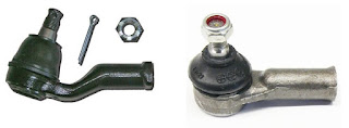
So while fail number two was imminent, I'd finally managed to catch up with myself and not fall into that particular hole. The solution is to use an MX5 TRE, these are angled in the same way as the upright. This means that at full droop, the TRE isn't at full travel. This is how the MX5 (left) and Sierra (right) TRE's compare;


The difference in angle is quite plain to see. The only thing is, the difference in internal thread isn't so plain to see!!!

Yep, although I had an Escort rack, and Escort extensions, they won't screw into the MX5 TRE's. What's more, as I mentioned above the Escort extensions were too long. I couldn't have used ANY TRE let alone an MX5 one.

Then I found out about thelatheman, an Ebay seller in Lancashire who does lots of custom lathe work. And what's more, after asking him whether he could do what I want, he actually pointed me to an Ebay item that was exactly what I was after! It was a shorter extension, with an internal thread for the Escort thread, and an external thread to fit the MX5 TRE. They are a bit more expensive (£37 vs the £15 I paid originally), but since it's the best/easiest/quickest option, it was a no brainer really. So I'm now just short of £60 lighter, £21 for a pair of MX5 TRE's and £37 for the extensions. Fingers crossed they arrive by the weekend and I can try them out.

Trial fit for suspension and bodywork

Now I've got my HSR body (woohoo!) and my bike has been sold (boohoo!), I can finally get round to fitting the body and seeing what work needs to be done. And to be honest, it's looking quite good...


This is the narrow body sat on an SSC based MX5 roadster. It was easy to see what work is to be done, mainly around outriggers to carry the base of the bonnet, a front mount for the hinge, and maybe some bracing along the trailing edge. As you can see on both sides the wheels stick out, this was more or less what I expected. There's a few options here, either attach some fender extenders (chrome ones would be very interesting), or swap the wheels for something with a lower offset. I'll deal with that afterwards though, at the moment I'm just happy the positioning is good.

In this pic there is a piece of metal going from left to right that is clamped under the chassis, and another at the front doing the same. These will be where the outriggers are going to sit.


This is the height of the bonnet when the bottom edge is in line with the chassis (you can make out the clamped bar to the right of the picture). Having said that, it's the rear shell that needs to be put in place first, I've not been able to do that purely because the chassis isn't finished.


It's certainly an interesting view from the drivers seat!

I also trial fitted the suspension, front...


And rear...


I'm glad I did this though, as I wanted to make sure I had everything available. Basically I have a bag of nuts and bolts, and as I build things I've been using the fixings to test out how everything goes together, then taking them apart and putting them back in the bag. The only problem is that I've double used some of the bolts, so when it came to put everything together at the same time I was short of quite a few bolts!!

So, in no particular order, here are my new 'to do' items;

1. Buy TRE's. I spent so long tracking down the front upper suspension arm track rods that I forgot the steering rack needs them too!!
2. Buy proper extenders for the TRE's. This one is an interesting one, I'll talk about this in the next post.
3. New bolts for the rear upper suspension mount. The block in the picture above holds the upper rear suspension arm, the MX5 upright, and the suspension coilover. Problem is the bolt that I had available doesn't go through them all. So I need a new pair of bolts for that. 
4. Diff bolts. As mentioned, I've used these diff bolts in several places, so I now need some for the actual diff!!
5. Steering rack fixings. Same again, double used.
6. Seat fixings. OK, they're not related to this, but I had to get some. That will be in the next next post.

Overall I'm so impressed with the bodywork, there's plenty of room available for the engine, I don't have to worry about radiator fittings, and most of all I won't have to deal with some of the sharp edges that most seven's have to sort out for the IVA. I have different ones to sort (I already have scratches and cuts from the body itself) but I'm hoping there will be less of an issue. 

Saturday 23 June 2018

I have a body!!

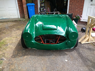
The body has arrived;


I didn't realise the kit came with a dashboard blank or aeroscreen, so that's an added bonus. I don't think I'll be using the aeroscreen though, I'd prefer a full windscreen. It's a nice colour, just the moulding lines need a bit of work. Then again, I didn't expect Ultima levels of moulding anyway so I'm happy.

Of course, with the chassis not quite complete, I can't do much more now. My bike is getting sold, then it'll be a sort out of the garage in order to get the chassis off the build table and then this on top of it. Once this is fitted I should have an idea where the rest of the parts need to go.

So for now, no more updates until the bike is gone...

Monday 28 May 2018

Steering complete

The steering column is now in place, along with the 10 degrees of deflection required for IVA. Obviously this pic exaggerates the angle;


But it has been measured and should be fine. The upper steering column is fixed at the top with the original sliding bolts which will disengage in the event of a crash. The lower fixing of the steering column is an exhaust clamp, again allowing the crush section to behave as it would have done in the MX5.

The upper part of the lower steering column is then supported by the bearing attached to the firewall. I did wonder why this was here as the column seemed pretty solid without it. But I guess belt and braces never hurt anyone. 


The bottom is standard fare, with the N pattern steering rack mounting welded into place. The left hand rack mount is actually the old MX5 rubber mounting, it fits the Escort rack perfectly. I need to grind down a weld to get it to mount flush though. From memory the right hand rack mounting on the MX5 was just a bolt, so that can't be reused. I'll make something out of metal for that side, not a huge job. 


For the next job, I need to mount the fuel tank. I've found someone on Ebay that makes fuel tanks for around £60, with an extra £15 for postage. He's only in Nottingham so I'll drive up and pick it up.

I need to make a frame for the tank. This is where I've moved quite a bit away from the plans. Because I have no need for a rear frame for the standard Seven tub, I've not actually got anywhere to put the gas tank. The tank sits behind the diff, sticking out of the back of the car. So I need to rebuild the back in such a way that it's as supportive as the original design, but doesn't use the rear hoop. Shouldn't be too difficult...

Friday 25 May 2018

Steering angle

The steering rack is now in place and bolted up, and I have a problem...

As part of the IVA regs the steering column needs to have a deflection angle. This is so in the event of a head on collision, the steering column doesn't head directly towards the driver. (If only Senna's mechanics had that plan 😢 ).

Unfortunately, me trying to get everything 'just right' means that I've actually lined things up almost perfectly, IE no deflection angle. Which means I need to make some modifications.

The steering rack is in the right place, and cannot realistically be moved. I don't want the steering travel to be different between left and right. The tube between the universal joints can't really be moved either, it has the chassis one side and the engine the other.

What can be moved is the upper steering column. If I move the bottom joint of the steering column out towards the chassis wall, the angle between upper and lower columns will increase. But if I move the bottom joint, the steering wheel will be crooked. Last time I had that I was in an '85 Vauxhall Nova, and the whole drivers side was tipped towards the centre because the front wheel was in the way!

But it looks like I have no option, so I'll chop off the lower bracket and reweld back in the right place. Tomorrows job...

(Tomorrow)


Five minutes with a photo and some powerpoint boxes shows I have 8 degrees deflection with the brackets as I've welded them. So I've chopped off the bracket that is in that photo, and I will need to move it to the right just an inch or so to get the 10 degrees. 

Tuesday 17 April 2018

Vernier

A while back I bought a vernier caliper from Aldi. It worked well, but the digital aspect of it was not designed for a garage, and died pretty quickly. So I thought I'd buy a standard one and hopefully get a decent one. Boy, was I wrong...


The scale is way out when set to zero, and no option to recalibrate it. So, time to find out what I can do, without having to resort to returning it.

Sunday 8 April 2018

Universally jointed


I had to post a picture of this, it's a remarkable piece of kit. It fits exactly as expected, and with bolt cutouts on both splines and drilled holes on this it'll be nice and secure. Looks like an M8 hole drilled through for a nut and bolt, while a threaded end might have been better I kind of prefer the need to add a nut.

The steering column has been chopped in half and marked for the 60mm lengths that need to be inside the thick wall tube. I've chamfered the ends slightly so it should be easy to fit. I'll then cross drill the tube and add some puddle welds as well as welding the end.

I've also done a red oxide coat on the rear suspension parts, they'll need a second coat then gold hammerite. The pedal box gets the same red oxide base but with a black top coat (it'll be deep in the foot well so no need for anything flashy). Time to get back on to the list and see what's next.

Tuesday 3 April 2018

Steering

I think my next job is steering, so there's a few things to sort here. First thing is mounting, the standard bracket is renowned for bending and letting the rack wander, and that's not what you want if it's the only thing keeping the car going in a straight line. Some simple braces and/or reinforcement will do here.

The steering column has already been fitted, and makes use of the collapsible column as a safety feature. The second feature will then be a universal joint to put a bend in the routing. And therein lies the problem...

MX5 steering columns are finished with a 5/8" x 36 splined end. Mark 2 Escort racks are finished with a 9/16" 36 splined end. Neither the standard Escort or the standard MX5 UJ's would work. And besides that, the bar is too short to get from one to the other!

The solution for the latter is to cut the bar and weld in a thick wall tube to extend it down to the rack. But there's no point in using the splined end if it won't fit to a UJ that can then go on to the Escort.

After a quick ask around on locostbuilders (the bible for home builders!) a kind gentleman gave me the name of a steering specialist who, purely by coincidence, is just down the road in Birmingham. They stock (amongst other things) a 5/8" to 9/16" UJ. Hopefully the price will be similar to the Rally Designs joint which is £24 plus postage. If it does work out to be a decent price, then I'll get one of those, extend the steering rack exactly as described in the book, and do away with any messing around with different sized shafts. Then all I need to do is buy some thick wall tube (15mm ID, 21mm OD seems to make sense although I may have to warm it up to get it to fit as 5/8" is 1.5875cm).

Oh, and before I forget, the specialist is Kiley Clinton Engineering. Fingers crossed for good news in the morning...

(update) £45 + vat... so not a huge saving over the spline shaft + coupler from Rally Design, but it looks like a far better solution. And a proper forged unit rather than just pressed steel. Now I just need to find the thick wall tube, and if it's anything like the other tube I've bought the post and packing will be more than the tube itself!

Monday 2 April 2018

Brake pipe straightener

A while back I purchased some rollers that were designed for 3d printing, but they fit brake pipes almost perfectly. So I was going to make a low cost version of this;

This particular one costs £140, I plan to make something very similar for less than £5. Watch this space...

More painting and 'to be done' list...


Chassis painting went ok, the welds look decent in the right places (some of the caps to seal the tubes are a bit 'rough', but they only need to be watertight rather than strong). And of course, when I took this picture I noticed the bit I missed on the lower suspension bracket...

The pedal box and the suspension parts also got a coat. So now it's on to the next job, which is.... erm... not sure!!

This is what I have left to do;


  1. Steering rack supports and brace. Three strips of metal to hold the steering rack. As with other items I'll be over-engineering this, as a common complaint is vague steering due to insufficient bracing.
  2. Brake hard line to flexi pipe support plates. Four small pieces of metal that will hold the joints between the flexi and hard lines. I need to figure out what these are, I think they're just 1mm plate with a certain sized hole in. The flexi pipe then feeds through and a d clip holds it in place.
  3. Engine mounts. Oooh, I may have to get the engine in place to figure out where these go. That'll be a new experience for me, the first time I've lifted the engine in place! I may have to wait until summer for that though, to get the engine and chassis into the same place in the garage will be impossible. 
  4. Gearbox mounts. As above, something to be done in decent weather.
  5. Roll bar. Now the book has the roll bar, but I want to wait until after I have the bodywork to do mine. And basically I'll just buy a ready made one.
  6. Pedal box fixings. A metal strip across the top with four welded nuts so it can be mounted in the car, not a big job. 
  7. Steering column modification. Not difficult, but has to be done properly. And I won't have the required tube so I need to buy some.
  8. Radiator and mounts. Completely forgot about this one... I guess I ought to find a suitable radiator.
  9. Propshaft to be modified. Definitely not a diy job, even if I felt confident enough to weld it I doubt I could get it balanced up afterwards. I'll find somewhere to get that done.
  10. Fuel tank. Steel is the obvious solution, but I might see if I can find something lighter.
  11. Fuel and brake pipes.
  12. Handbrake.
  13. Electrics. This can be an entire blog all on it's own!! 
  14. Bodywork. To be purchased, I wonder if this is the year I place my order at Stoneleigh. Best take my cheque book.
  15. Paint the rest of the chassis and the rear suspension parts. 
So overall not actually that much more to do. Some jobs I can't do, some jobs will take me five minutes. 

Sunday 25 March 2018

Uprights done


Well, that's the uprights finally finished. This cold weather was making painting very challenging, the hammerite was drying but staying soft rather than properly curing. Ah well, these will now go into storage somewhere until they're needed again.

The next job is to go over the chassis with red oxide primer. Because it's been stored in the garage for so long the front end has collected some surface rust. So I'm going to take this opportunity to go over the chassis with a fine tooth comb. As I clean the rust off, I'll check all the welds and fix them as required, then give everything a coat of primer. I realise I'll need to clean it back off when I have to weld things on, but at least it won't get any more rusty.

The only problem is that because I've been working on the back of the car, all the garage 'stuff' has migrated to the front. And I don't really want anything covered in primer. Time for another garage sort out I guess.

Sunday 25 February 2018

Hub painting


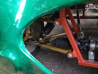
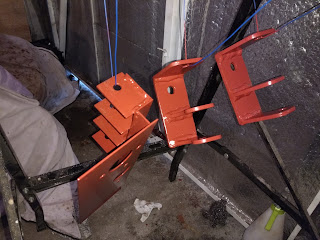
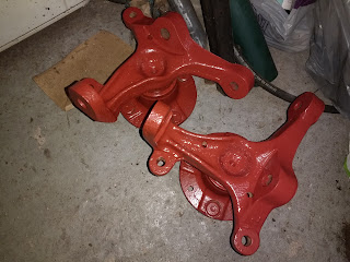
The hubs are coming along nicely, a couple of coats of red oxide and then gold top coat (yep, sticking with the iron man colour combo!). Despite the photos they actually are the same colour, I think the front hubs had just dried a bit more by the time I took the photo. I've also included a couple of suspension brackets that needed to be done. I still have all four rear suspension arms to paint, but that needs a bit of set up. I might try and do that Wednesday, depending on whether the weather leaves me stranded in Leeds.

Oh, and a note to my past self... remove the driveshaft nut BEFORE dismantling the car!! I've had to do all my rear end work with driveshafts attached to the rear hubs. It's been fine when sorting out the suspension linkages and similar, but a pain in the bottom when I only need the hub on it's own. And I still don't know what the bearings are like!! They seem to turn quite smoothly, but it could be very different when the engine is trying to turn the wheel to move the car.

Ah well, not something to think about for now.

Sunday 18 February 2018

Breaking news...

It is with regret that I must announce the passing of the brake disc shields. I did all I can to save them but they were too far gone...

To be fair I actually didn't try too hard, I just got fed up of trying to get them clean so they got removed. Five out of six bolts came undone with some persuasion, the sixth needed it's head ground off. No matter, it's not as if I'm going to put replacements on!

Front hubs are now back in the bucket of Deox C for their last soak before removing, cleaning drying and painting.

Music musings....

Yes I know, audio options are not exactly top of the list when it comes to kit cars. However, the MX5 donor seats come with speakers in the head rests, and it seems appropriate that I make them functional for those longer journeys.

The plan is to have an 'invisible' audio system, that is entirely driven from my phone. Bluetooth connection to a pre-amp receiver, to a small amp that drives the seat speakers. It's similar to what I have in the tintop at the moment, a Bluetooth receiver going to it's aux-in. It obviously still needs a power source, but that's easier than an audio source.

Problem is, it's not the best quality, so I've been trying a few things. First test was to try an alternative to Bluetooth. As people may know, phones are powered by USB, but in my tintop at least it causes a horrendous earth loop when the phone is plugged in (partly why I use Bluetooth, no earth loop!). So headphone out is a no-no (unless I resolve the loop part). I do have a USB DAC which works, so I bought a phone USB hub off Ebay and tried it. The DAC works fine (plug and play, excellent!), and the sound quality is actually really good. But as soon as I plugged power into the hub, I got a high pitched squeal.

It also turns out the hub can't actually supply power, so I'll have to see what the seller says about that. If I can resolve the squeal, then it might be useful to be able to just plug the phone in and go.

To summarise, I can go with;

  1. The bluetooth receiver which isn't the best quality but is easy to get working.
  2. The headphone socket which is better quality but causes an earth loop.
  3. USB DAC which is the best quality but I have a faulty hub so couldn't power the phone.
Time to jump on Ebay and see whether it's actually faulty or whether it's just something about my phone.

(Update). The seller accepted it being faulty and I got a refund. I've now ordered a different hub so I'll see if that is any improvement.

Saturday 17 February 2018

Hubs

The next bit of cleaning is the front and rear hubs. These came from the donor MX5, and while they were in usable condition, a few years of sitting around has left them dirty and rusty. In particular the brake dust guard on the front hub is pretty bad. Then again, that's about normal for most cars, and I tend to remove them when they get too bad. Fingers crossed these might be ok, but only time will tell.

The rears were first, an overnight soak in deox c rust remover got rid of a lot of it. I did make a bit of a mistake though. You're meant to scrub the metal on a regular basis to dislodge the bits of rust. I did do this, but I was scrubbing it in the rust remover bath. So basically I was giving the rust remover so much extra work to do!! What I should have done is took it out and scrubbed it separately, that would have allowed the rust remover to only work on attached rust. As it stands the rears are now mostly done, but I've got through an entire bottle of rust remover doing it.

For the fronts, I'll be doing it properly. I have one bucket of 1:20 rust remover (1 part remover to 20 parts water), then in another bucket I have water with washing up liquid. There's a hub in each of them now, what I'll do is every so often swap them over, and whichever one ends up in the water bucket will get scrubbed. Hopefully this will make the rust remover go a bit further.

Having said that, the rust remover has been truly excellent. It's not overly cheap (and even more expensive if you use it wrong!), but being able to just leave the part in a bucket to sort itself out is really useful. I had planned on electrolysis first, but I was having real trouble with finding a location where it wouldn't get interfered with by wildlife or the elements, where I can DC power safely, and where the gases can escape. At least the rust remover can just be done in the garage.

Pictures of the hubs to follow, I should do a before and after but because I didn't do a 'before' it will be just an 'after'. Then on to the next job.

Saturday 3 February 2018

And done!


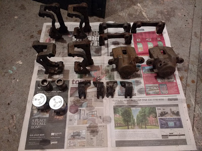
Well, I think they came out quite nice. All seals and rubbers replaced, I reused the pistons and sliders because despite them looking pretty rough initially, they cleaned up very nicely. New bleed nipples (the old ones were just asking for trouble), but the handbrake mechanisms just needed a bit of cleaning and greasing. The last bit to add are the small chrome pad sliders, I could probably just put them on when the pads go on. They were similar to the pistons, just needed a bit of a clean.

They're now in sealed bags where they will hopefully be ok until I come to use them.

Next job, steering rack. Hmm, I wonder where I left the track rod ends that I bought...


Sunday 14 January 2018

And cleaning...


The cleaning is going well, although it's proper back breaking work!! This is the result of a weekends hard slog. Turns out the best stuff so far is the Deox-c that I had bought a while back. Whilst it doesn't seem to work immediately, what it does is loosen the rust so it can then be rubbed off with a green scouring pad (the washing up kind of pad). What was apparent though is that the bare metal very quickly gets a haze of rust almost as soon as it comes out of the solution. What I'll need to do is remove each part in turn, give it a scrub and dry then paint it.

In terms of other parts used, I've bought all new seals (£30 for all four corners), new bleed nipples (a fiver) but I'm going to reuse the sliders as they seem ok (apart from needing a clean as above). I also have new copper washers (no brainer for that one to be honest). I'll be reusing the various bolts as well, again they just need a good clean.

And the rears are a challenge. As I figured out, the pistons are screwed in, so it took the whole of two minutes to remove the pistons. Problem is, the bolt that screws them in also needs to come out (there's a seal that I think has perished on one), but it needs a circlip removing that is inside the caliper. I've ordered a pair of internal circlip pliers that I am hoping are narrow enough and long enough to get inside. Once they're out, I can replace the seal and check the handbrake mechanisms.

Apart from that, I seem to have lost a rear caliper bracket (but I still have three!), and I may have to replace the rear pistons as I'm not sure they are usable.

In other news, I am now the owner of an Escort Mark 2 steering rack, obtained for the princely sum of £40!! It looks almost brand new, it still has end caps on and protective paint on the threads, so I'm not even sure it's ever been mounted. I'm going to remove the bellows to peek inside, but if everything checks out I won't be doing much else to it. Oh, apart from finding some decent mounting brackets. I'm tempted to go for solid mounts, but I'm also thinking it might make the ride a bit harsh.

Sunday 7 January 2018

Cleaning...

One of the things I've yet to do is clean up the donor parts. In this case it's mainly the brakes. The ones that came off the car were definite MOT failures, but when I took them off I was hoping they'd clean up. Having said that, I also bought a complete extra set of brake calipers, discs and pads for £80, so I have double of everything.

And I needed it!! The first front caliper came apart quite easily (if a little mucky). I did the compressed air trick to shift the piston, and it came out with an almighty crack. I was off to a good start.

The second one I picked up was missing a dust seal, not good. Turned out the piston wasn't going anywhere, in or out. So I removed the sliders, carrier and other spare parts, and marked that one for the bin.

Third one wasn't much better, it had a dust seal but was ripped. So again I scavenged what I could and put the caliper aside. So that was a working left caliper, a failed right, a failed left.

Thankfully the last right hand caliper piston also came out quite easily, although the sliders didn't. Still, overnight soaking in plusgas should solve that one.

I'd made enough mess by this point so I stacked up the rear calipers ready to dismantle them sometime today. Then it's a good scrub and grind to get rid of the rubbish, followed by a coat of paint. The new front seals are on their way (£14 for both sides including slider boots).

By the way, for anyone using compressed air for removing pistons, heed the warning about them coming out with force. If there isn't anything to stop the piston coming out, they will end up flying. Fortunately the front caliper was big enough to contain the piston, however I can see the rear piston is small enough to shoot straight out. Leave a brake pad or flat metal in the caliper to stop it doing damage. And keep your fingers out of the way!

Next job after the calipers, removing the surface rust off the chassis and putting the first coat of oxide on it.

(A quick note to self... the rear pistons won't 'blow' out, they're fixed in with adjuster screws. In some ways that makes them easier to dismantle, although it still won't work if corrosion has set in. Anyhow, that's this weekends job).

Monday 1 January 2018

Fixed pedals and new holes

Quite a productive hour today;


The clutch pedal has been straightened and welded up so it sits in between the brake pedal and the transmission wall. The hole has been cut for the brake master cylinder, and I've positioned the gas pedal for fitting tomorrow. 

The gas pedal should be even easier than I expected;


Basically I need to make two brackets off the cross member to hold the spring where I've clamped it. It did occur to me that the cable mount is at an odd angle, but it can be quite easily bent to shape. 

The clutch master cylinder is on order, so I'll wait for it to appear before cutting the clutch holes. Then I need to make stops for all three pedals. Bent pieces of metal work for the manual, so I'll do the same!!

Then I need to figure out how to bolt the entire unit to the chassis, shouldn't be too difficult but I want to make sure it's reinforced. 

Two down, one to go (ish)


Well, there you go. Two pedals mounted on the back plate...

So a few things spring to mind. The plates were a good choice, the thing is rock solid. If I can finish the top and bottom bolts then there will be no flex at all. On the flip side, the welding was awful. Good penetration (pretty patterns showing through the other side), but so ugly it needs cleaning up.

But the main issue is the clutch pedal. I had hoped to retain the angle of the arm to keep the master cylinder out of the way of the engine. But having it in the right place actually has the two MC's in the same place. So I had to move the pedal 20mm to the left, which means the foot plate itself is right against the side of the foot well. Unless I want to spend all my time pressing the clutch with the side of my foot, it needs to be moved.

Tomorrow I'll cut off the plate (again!!) and reweld it in a better place.

But thankfully the brake pedal sits underneath the steering column absolutely perfectly, so I'm well happy with that. And plenty of space for the gas pedal, which will hang from above.

Hmmm, I need a shoe to measure...

Here's to getting the car finished this year! Well, at least moving under it's own steam, actually getting it finished is in the hands of VOSA and DVLA so that could be any time!